Table 2-2. rear panel dip switch functions, 1 independent operation, Independent operation -3 – KEPCO RA 19-1U Operator Manual User Manual
Page 19: Rear panel dip switch functions -3, Ar. 2.4.1), R. 2.4.1 (in
RA 19-1U 020413
2-3
2.4.1
INDEPENDENT OPERATION
The rack adapter is preconfigured at the factory for independent operation of all slots. DIP
switch positions 3, 4 and 5 associated with each slot must be set to OFF (open) for each power
supply to be operated independently.
NOTE: Either local or remote sensing must be connected for the 1U HSF power supplies
to work properly.
The rack adapter is shipped from the factory with each power supply position configured for
local sensing (see Figure 2-2). Sensing for each slot can be configured independently:
• Local sensing using rear panel DIP switches
• Local sensing using external jumpers connected to the I/O mating connector or the DC
OUTPUT terminal block.
• Remote sensing
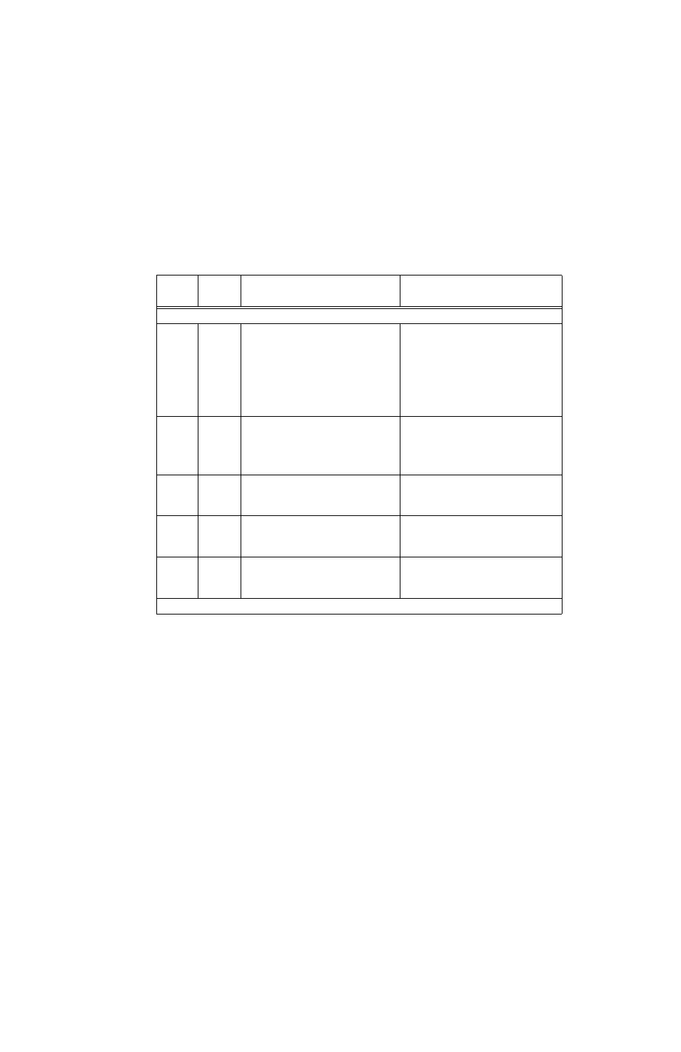
TABLE 2-2. REAR PANEL DIP SWITCH FUNCTIONS
DIP
SWITCH
POSITION
FUNCTION
DIP SWITCH SET TO ON (CLOSED)
DIP SWITCH SET TO OFF (OPEN)
NOTE: BOLD TYPE INDICATES FACTORY SETTINGS.
1, 2
Local /
Remote
Sensing
Selection
Required ON for independent operation with
Local Sensing. Position 1 connects V+ to S+,
Position 2 connects V– to S– (see PAR.
2.4.1.1).
Position 1 and 2 required OFF for:
a) Independent configurations using Remote
Sensing (see PAR. 2.4.1.3).
b) Independent configurations using Local Sens-
ing with user supplied connections from V+ to S+
and V– to S– (see PAR. 2.4.1.2).
c) All parallel configurations (sensing must be
established using external wires) (see PAR.
2.4.2.3).
d) All series connections (see PAR. 2.4.3).
3, 4
Connect
Sense
+ and –
in parallel
Required ON for parallel configurations using DIP
switch settings to connect the sense leads in par-
allel. Position 3 connects +S to adjacent slot +S,
Position 4 connects –S to adjacent slot –S (see
PAR. 2.4.2.3.1 for local sensing, PAR. 2.4.2.3.3
for remote sensing).
Position 3 and 4 required OFF for all configura-
tions except parallel configurations using DIP
switch settings to connect the sense leads in
parallel.
5
Current
Share
Required ON for parallel operation (connects cur-
rent share lines in parallel) unless connections are
made via external wires (see PAR. 2.4.2.2.1)
Required OFF for
a) independent and series configurations.
b) Parallel configurations using external wires
to connect current share lines in parallel.
6, 7
Close on
Failure
Alarm
When set to ON, allows a single alarm to provide
failure indication (contact closure between N.O.
pin and COM pin) if any one of many power sup-
plies fails (see PAR. 2.4.4.1).
When set to OFF, individual power supplies
produce closure between I/O connector N.O.
and COM pins upon failure (see PAR. 2.4.4.1).
8
** Open on
Failure
Alarm
** When set to ON, allows a single alarm to pro-
vide failure indication (contact open between N.C.
pin and COM pin) if any one of many power sup-
plies fails (see PAR. 2.4.4.2).
** When set to OFF, individual power supplies
produce open between I/O connector N.C. and
COM pins upon failure (see PAR. 2.4.4.2).
** Not applicable for HSF-1URX and -1URY models (see PAR 2.6).