En g li s h swivel conduit mounting – RISCO Group Wireless WatchOUT PIR 312PR User Manual
Page 11
WatchOUT PIR Installation Manual
11
E
n
g
li
s
h
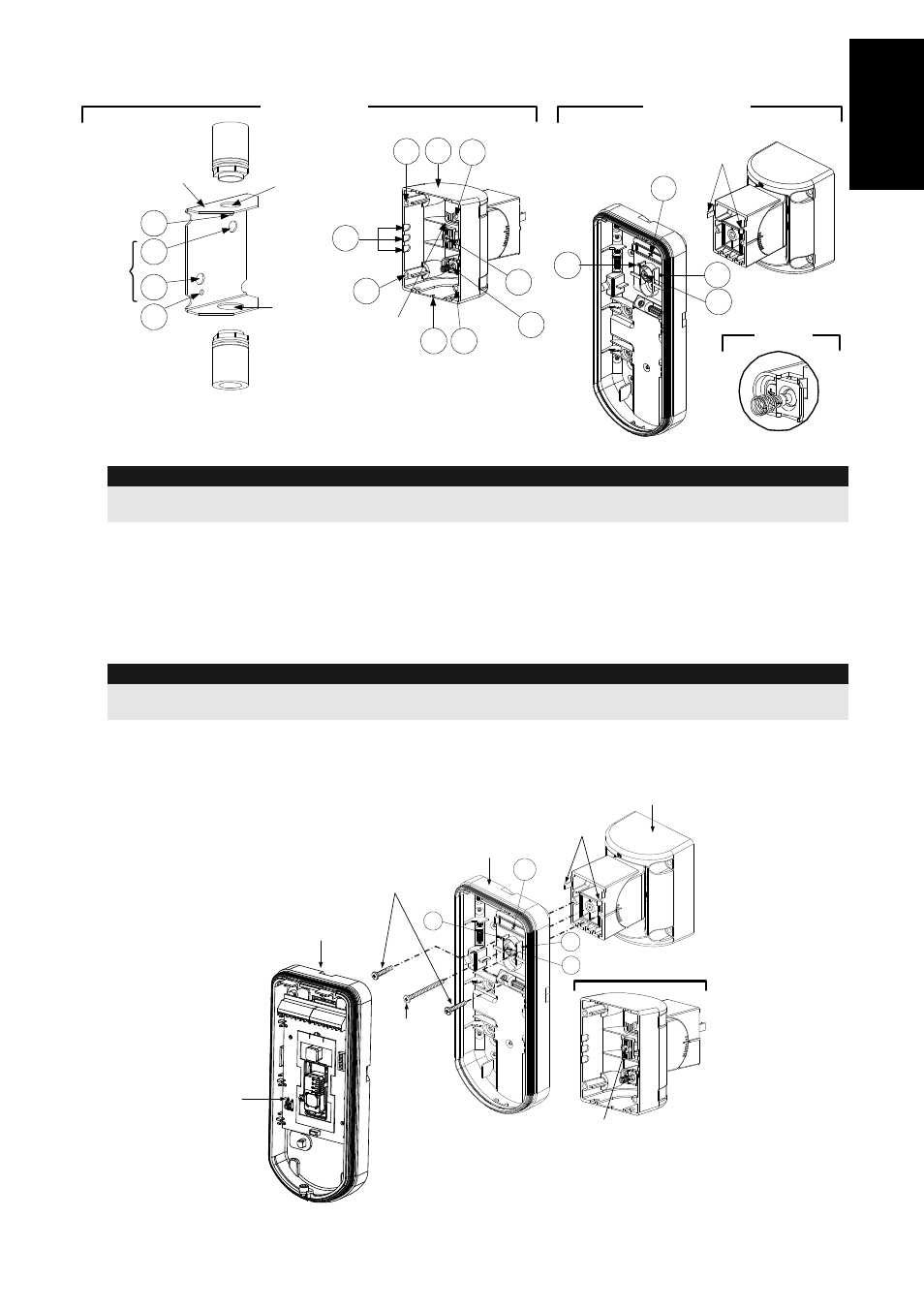
Swivel Conduit Mounting
(using Conduit Metal Swivel Adaptor - CSMA, Figure 8, Detail A)
S1
S2
S3
S9
S8
S7 S6
S5
S4
Tamper
(see Detail C)
Swivel Wires
Passage
Tamper
Spring
Holes
Ø
21 mm
Ø
16
mm
CSMA
M1
M2
M3
M4
Detail
A
Detail
B
S1
W1
S2
S3
Snaps
Standard Swivel
Detail
C
Figure 8
Note:
The CSMA is required when wiring is in a pipe external to the wall. It should be ordered separately P/N
RA300S.
a. Choose the direction upon which to mount the CSMA according to the required diamet er:
16mm (0.63 inches) or 21mm (0.83 inches).
b. Insert conduit to the CSMA.
c. Secure CSMA to the wall through points (M1, M4).
d. Insert external cables and tamper wires from the conduit through the swivel wires passage
of the swivel (Figure 8, Detail A).
e. Secure swivel to the wall through holes S1, S3, S6 and S8.
Note:
The Tamper spring S5 (Figure 8) should make contact with the wall through the tamper spring holes M2 or
M3 on the CSMA. Make sure to hear the tamper "Click" when connecting to the wall.
7.
Insert tamper wires and external cable wiring from Standard Swivel through knockout W1 on
the external base (Figure 8, Detail B).
8.
Connect the external base to the swivel using the dedicated snaps (Figure 9).
External Base
Angle Locking
Screw
(See Note 2)
See Detail A
Swivel to External Base
Connecting Screws
Detail A
Swivel Assy
Connecting Screw
(See Note)
Snaps
S1
W1
S2
S3
Internal Base
PCB
Figure 9