Terminal wiring, Changing back tamper position – RISCO Group WatchIN Industrial Grade 3 Detector User Manual
Page 6
WatchIN Installation Manual
4
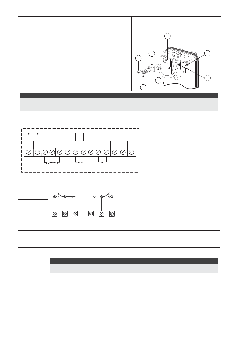
Changing Back Tamper position
The back tamper is by default secured on the right
side of the internal base (Rear view). If you wish to
move it to the left side (rear view), do the following
(Figure 5):
1. Remove tamper screw 1 in order to release the
tamper from position 7.
2. Ensure tamper spring 2 rests over tamper wire
base 4.
3. Ensure plastic tamper bracket 3 rests over both
2 and 4.
4. Secure tamper screw 1 into 3 over position 6.
Figure 5
Left
Side
Tamper
Right
Side
Tamper
3
6
1
2
4
7
5
Notes:
1. Verify that you hear a "Click" when attaching the tamper spring to the wall.
2. For pole installation, the tamper can be moved to the bottom right-hand side of the internal base.
Terminal Wiring
+
-
SET/
UNSET
AM
TAMPER
FREE
(YEL)
12VDC
N.C.
WatchIN - PCB
N.O . COM N.C.
FREE
(GRN)
LED
ENBL TEST
N.O.
N.C.
N.C.
+,-
12 VDC
N.O
Form C relay, 30VDC 1A
NORMAL
N.O
COM
N.C
ALARM
N.C
COM
N.O
COM
N.C
FREE YEL
This terminal is a free pin that can be used to connect wires and EOL resistors
TAMPER
N
.C relay, 24VDC , 0.1A
FREE GRN
This terminal is a free pin that can be used to connect wires and EOL resistors
AM
Normally closed AM relay output (
24VDC, 0.1A
) indicates Anti Masking alarm or
any trouble in the detector.
Note:
When a vibration detector is installed and DIP 8 is defined as Enabled this relay also opens
momentarily when vibration event occurs.
LED ENBL
Used to remotely control the LEDs when DIP 1 is set to ON.
Enable: input is +12V OR no terminal connection
Disable: Connect the input to 0V
TEST
Used to perform remote alarm testing to the detector by applying 0 volts to this
terminal.
Success: Alarm relay is momentary opened
Failure: AM relay is momentary opened