Pd865 snooper modbus, Serial input meter instruction manual – Precision Digital PD865 User Manual
Page 18
PD865 Snooper Modbus
Serial Input Meter
Instruction Manual
18
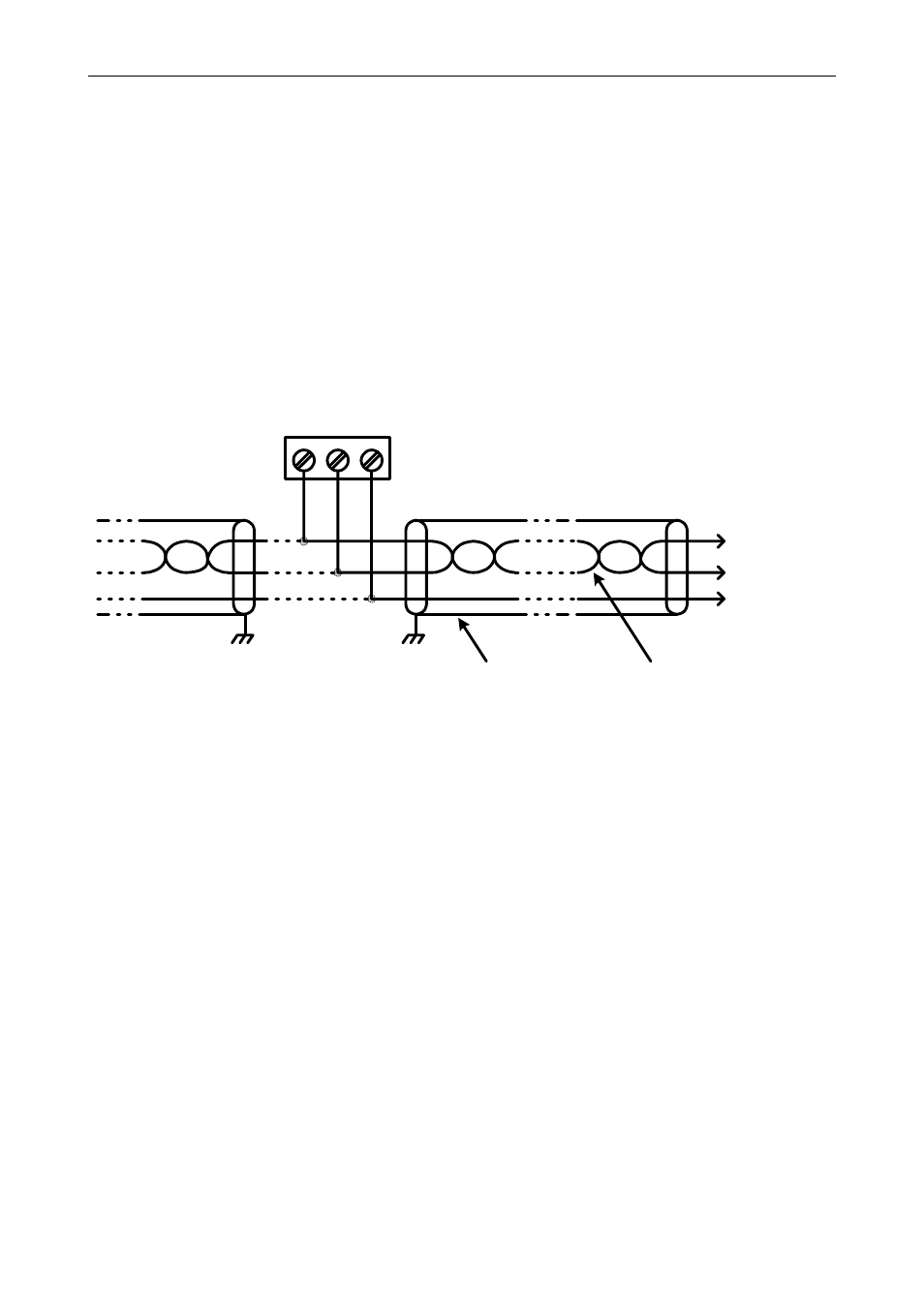
Serial Connections
The PD865 is connected to an RS-485 bus with up to 32 nodes. For
systems consisting of more than 32 nodes, RS-485 repeaters are
necessary. Wiring connections to the PD865 are made via the three
position screw terminal connector labeled RS-485. Please refer to the
EIA-485 standard for complete specifications for balanced digital multi-
point communications. The use of shielded twisted pair cable is
recommended to protect the data signals from electrical interference.
For long wire runs it is good practice to terminate the bus at both ends
with a resistor connected between D+ and D- that matches the
characteristic impedance of the cable. A typical termination resistor
value is 120
Ω.
RS-485 Connector
D+ D- G
1 2 3
Shield
Data +
Twisted-Pair
Data -
Common
Figure 6: RS-485 Connection
For point-to-point (non-multipoint) serial communications with RS-232
data communications equipment (e.g. a personal computer), an RS-232
to RS-485 converter (e.g. the Precision Digital PDA7485) is required.
When using the PDA7485, connect the PD865 according to the
PDA7485 wiring diagram for a two wire RS-485 application.