Multi-Contact MA223 User Manual
Page 5
Advanced Contact Technology
www.multi-contact.com
5 / 8
10
max. 5 mm
+0
.2
- 0
,4
Ø1
2,
5
11
12
13
14
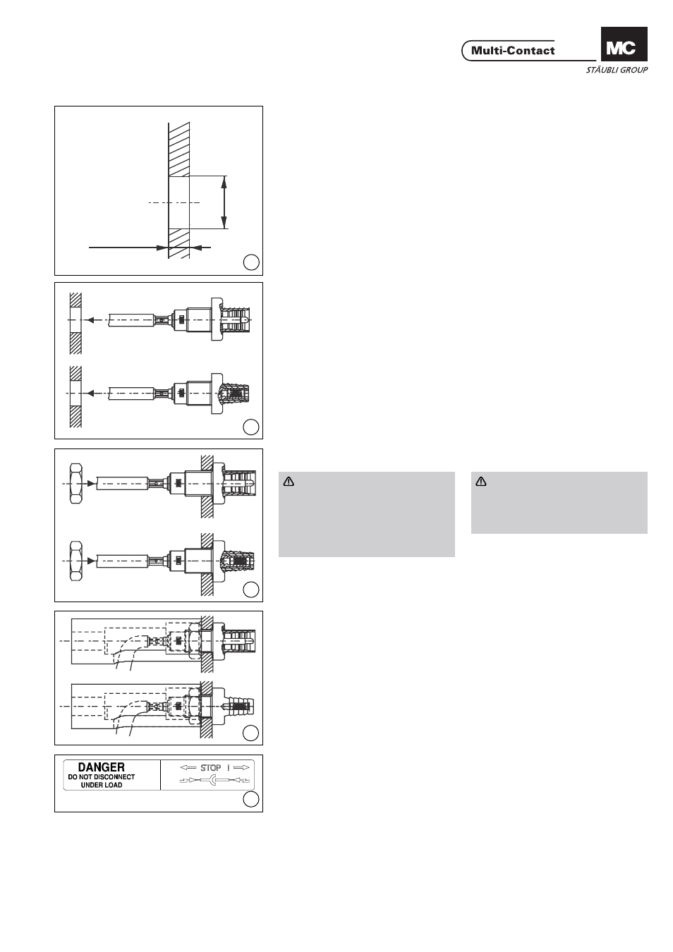
Montaje de los conectores
empotrables
Assembly of panel recepta-
cles
(ill. 10)
Taladrar la pared del panel
(Ø 12,5mm).
(ill. 10)
Drill a hole (Ø 12,5mm) in the wall of
the housing (max. 5mm wall thick-
ness).
(ill. 11)
Introducir los conectores empotrables
junto con el cable engarzado en el
taladro practicado.
(ill. 11)
Feed crimped cable with panel recep-
tacles through the drill hole.
(ill. 12)
Colocar a mano la tuerca hexagonal.
Atención:
Es muy importante fi jar los co-
nectores empotrables con ayuda
de las tuercas de plástico que
acompañan al suministro (las dos
piezas se complementan una con
otra).
(ill. 12)
Screw on the hex. nut by hand.
Attention:
It is important that the panel
receptacles are fi xed with the de-
livered plastic nuts. (Parts match
each other).
(ill. 13)
Apretar la tuerca con la lave dinamo-
métrica. Par de apriete 2Nm.
(ill. 13)
Tighten nut with the torque spanner
(tightening torque 2Nm).
(ill. 14)
Enganche el adhesivo „DANGER – DO
NOT DISCONNECT UNDER LOAD“
en la carcasa de la aplicación lo más
cerca posible de los paneles fotovol-
taicos.
(ill. 14)
Attach enclosed sticker „DANGER
- DO NOT DISCONNECT UNDER
LOAD“ to the applicance housing as
near as possible to the PV panel male
receptacle.