N r b m, Installation and assembly – MCZ Vivo 90 Pellet Comfort Air User Manual
Page 30
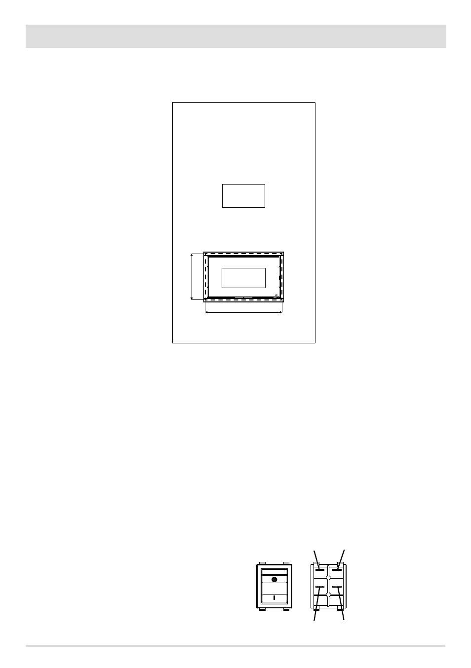
875
490
N R
B M
28
7-INSTALLATION AND ASSEMBLY
PRODUCT HOUSING HOLE
The hole to be made on the wall is 875*490 mm. These measurements allow the frame to cover the gap that remains between the product
and the hole and also allow the product to be removed if maintenance is to be performed and/or parts are to be replaced.
FRONT CHUTE ASSEMBLY
Should you opt for positioning the pipe at the front act as follows:
• Connect the pipe supplied to the product ensuring it is rotated to the front, and fasten it with the clamp.
• Connect the pipe to the mouth of the hatch structure by means of the clamps supplied.
• Position the piping in order to make it accessible when cladding is completed and in order to be able to fix the hatch structure, to the
hole arranged on the wall of the cladding.
• To mount the outer hatch, which should only be done when cladding is completed, refer to the suitable paragraph.
CONNECTION OF SWITCH AND CONTROL PANEL
The control panel and the switch are already fitted onto the pellet loading hatch and are already connected to the relevant cables by the
manufacturer. Take the switch cable and connect it to the socket at the rear of the product.
The panel cable instead must be connected to the electrical board in position 1.
To fasten the switch to the pellet loading hatch the cables must temporarily be disconnected. reconnect the cables to the relevant
terminals as shown in the figure.
N = BLACK
R = RED
B = BLUE
M = BROWN