Operation – Sealey TA303 User Manual
Page 3
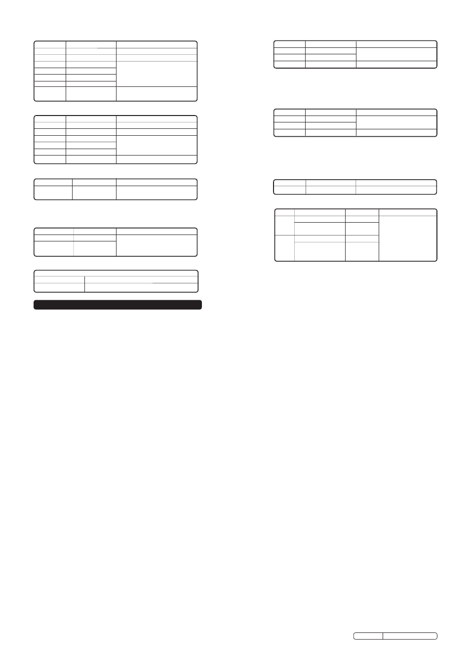
Range
Resolution
Accuracy
40.00mA
10uA
400.0mA
100uA
± 1.5% of reading ± 3 digits
20A
10mA
± 2.5% of reading ± 5 digits
Range
Resolution
Accuracy
40.00mA
10uA
400.0mA
100uA
± 1.8% of reading ± 5 digits
20A
10mA
± 3.0% of reading ± 7 digits
Range
Resolution
Accuracy
400.0Ω
0.1Ω
± 1.2% of reading ± 4 digits
4.000kΩ
1Ω
± 1.0% of reading ± 2 digits
40.00kΩ
10Ω
± 1.2% of reading ± 2 digits
400.0kΩ
100Ω
4.000MΩ
1kΩ
40.00MΩ
10kΩ
± 2.0% of reading ± 3 digits
DC Current
Overload Protection: 0.5A/250V and 20A/250V Fuse.
Maximum Input:400mA ac rms or 400mA dc on uA/mA ranges,
20A ac rms or dc on 20A range.
AC Current
Overload Protection: 0.5A/250V and 20A/250V Fuse.
Frequency range: 50 to 60Hz
Maximum Input: 40mA ac rms or 400mA dc on uA/mA ranges,
20A ac rms or dc on 20A range.
Resistance (Auto ranging)
Range
Resolution
Accuracy
4nF
1pF
± 5.0% of reading ± 7 digits
40nF
10pF
± 5.0% of reading ± 7 digits
400nF
0.1nF
4uF
1nF
± 3.0% of reading ± 5 digits
40uF
10nF
400uF
0.1uF
4mF
0.001mF
±10.0% of reading ±10 digits
40mF
00.01mF
Capacitance (Auto ranging)
Range
Resolution
Accuracy
1.0~20.0ms
0.1ms
± 2% of reading ± 20 digits
Pulse Width
Range
Resolution
Accuracy
-30°C~1000°C 1°C
± 3.0% of reading ± 5°C / 8°F
-22°F~1832°F 1°F
(Meter only, probe accuracy
not included).
Range
Resolution Accuracy
rPM 4 600~4000rPM
1rPM
1000~12000rPM 10rPM
(x 10rPM)
±2% of rdg ± 4 digits
rPM 2 300~4000 rPM
1rPM
& DIS 1000~6000rPM 10rPM
(x 10rPM)
Temperature
Sensor: Type K Thermocouple
Range
Resolution
Accuracy
1.0mA typical 1mV
± 5% of reading ± 15 digits
Diode test
Open Circuit Voltage: 3.0V dc typical.
Effect reading: >600rPM
RPM (Tach)
Audible Continuity
Audible threshold:
Less than 35Ω
Test Current:
< 1mA dc typical
4. OPERATION
WARNING! Ensure that you read, understand and apply the safety and operational instructions in Section.1 before connecting the analyser. Only when
you are sure that you understand the procedures, is it safe to proceed with testing.
WARNING! risk of electrocution. high voltage circuits, both AC and DC are very dangerous and should be measured with great care. remember to
turn meter off when measurement is completed.
Note: If 'OL' (over limit) appears in the display during a measurement, the value exceeds the range that is selected. Change to a higher range.
Note: On some low AC and DC ranges, with the test leads not connected to a device, the reading may show a random fluctuating reading. This is normal and
is caused by the high input sensitivity. The reading will stabilise and give an accurate measurement when connected to a circuit.
4.1.
Mode Button (fig.1.2)
4.1.1.
Press the Mode button to toggle between:
AC / DC Voltage
AC / DC Current
resistance, Continuity and Diode measurements.
4.2.
Range Button (fig.1.3)
The range is automatically selected in modes where Auto-ranging is stated above.
4.2.1.
To manually select a range within a function, press the range button repeatedly until the desired range is selected.
4.2.2.
To exit the manual range mode and return to auto-ranging, press and hold the range button for two seconds.
Note: If the range is too high, the meter will be less accurate.
If the range is too low, the meter displays ‘OL’ (Over Limit).
4.3.
Hold button (fig.1.1).
The data hold function allows the meter to freeze a measurement reading for later reference.
4.3.1. Press the data hold button once to freeze the reading in the display. The indicator “hold” will appear in the display.
4.3.2. Press the data hold button again to return to normal operation.
4.4.
Peak Button (fig.1.5).
The peak measurement feature allows peak AC / DC Voltage or Current to be captured. The analyser can capture peaks as quick as 1 millisecond in
duration.
4.4.1. Whilst in AC / DC Voltage or Current measurement mode, press and hold the Peak button until CAL is displayed. This procedure will zero the range
selected.
4.4.2. Press the Peak button again and Pmax will display. Manual ranging is selected. The display will now update each time a higher peak occurs.
4.4.3.
Press the Peak button again and Pmin will display. The display will now update each time a lower negative peak occurs.
4.4.4. Press and hold the Peak button and Pmax or Pmin will switch off and the analyser returns to normal mode.
4.5.
Backlight Button (fig.1.6).
4.5.1. To turn the backlight on, press the backlight button.
4.5.2. To turn the backlight off, press the backlight button again.
4.6.
MAX/MIN Button (fig.1.4).
4.6.1. Press the MAX/MIn button to enter the MAX/MIn recording mode. The display icon MAX will be displayed. Press it again and MIn will be displayed.
The analyser will go to manual ranging and display and hold the maximum or minimum reading (as selected) and will update only when a new “max or
min” occurs.
4.6.2.
Press the MAX/MIn button again and a flashing “MAX MIn” will appear. The analyser will display the present reading, but will continue to update and
store the max and min readings.
4.6.3. To exit MAX/MIn mode, press and hold the MAX/MIn button for 2 seconds.
4.7.
AC and DC Voltage Measurement
4.7.1. Insert the black test lead into the negative “COM” jack and the red test lead into the positive VΩHz% etc. jack.
4.7.2. Turn the rotary switch to the V
AC
or V
DC
position as required.
4.7.3. Touch the test probes to the circuit under test (black test probe to earth or negative terminal) and read the voltage displayed.
Note: IMPORTANT: Voltage must be measured in parallel (red probe measuring circuit from power source).
WARNING: When measuring voltage, be sure that the red test lead is in the jack marked
VΩHz% etc.
If the red test lead is in the 20A or 400mA
jack, the user may be injured or the analyser damaged.
TA303 Issue no: 2 - 20/12/11
Original Language Version
Accuracy is given at 18°C to 28°C (65°F to 83°F) with less
than 70% relative humidity.