J and k type thermocouple input modules -16, 10 j and k type thermocouple input modules -16, 10 j and k type thermocouple input modules – Emerson ROC827 User Manual
Page 86
ROC827 Instruction Manual
Issued Mar-06
Input/Output Modules
4-16
Note
: All I/O modules are isolated on the field side. Be aware that you can
induce ground loops by tying commons from various modules together.
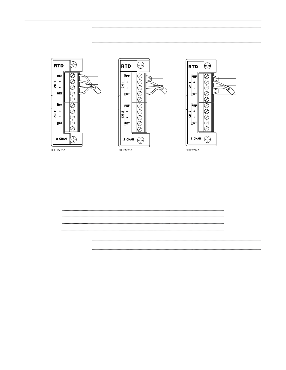
Figure 4-14. RTD Sensor Wiring Terminal Connections
Figure 4-14 and Table 4-2 display the connections at the RTD terminals
for the various RTD probes.
Table 4-2. RTD Wiring
Terminal
4-Wire RTD
3-Wire RTD
2-Wire RTD
REF
Red
Jumper to +
Jumper to +
+
Red
Red, Jumper to REF
Red, Jumper to REF
–
White
White
White, Jumper to RET
RET
White
White
Jumper to –
Note
: The wire colors for the RTD being used may differ.
4.10
J and K Type Thermocouple Input Modules
The five-channel J and K Type Thermocouple Input module monitors
either J or K Type Thermocouple (T/C). J and K refer to the type of
material used to make a bimetallic junction: Type J (Iron/Constantan) and
Type K (Chromel/Alumel). These dissimilar junctions in the thermocouple
junction generate different millivolt levels as a function of the heat to
which they are exposed.
The J and K Type Thermocouple Input module measures the voltage of
the thermocouple to which it is connected. The T/C voltage is measured
and a Cold Junction Compensation (CJC) correction factor is applied to
compensate for errors due to any voltage inducted at the wiring terminals
Jumper
4-Wire RTD
3-Wire RTD
2-Wire RTD
Red
Red
Red
Jumper
Red
Jumper