Emerson ROC827 User Manual
Page 54
ROC827 Instruction Manual
Issued Mar-06
Power Connections
3-10
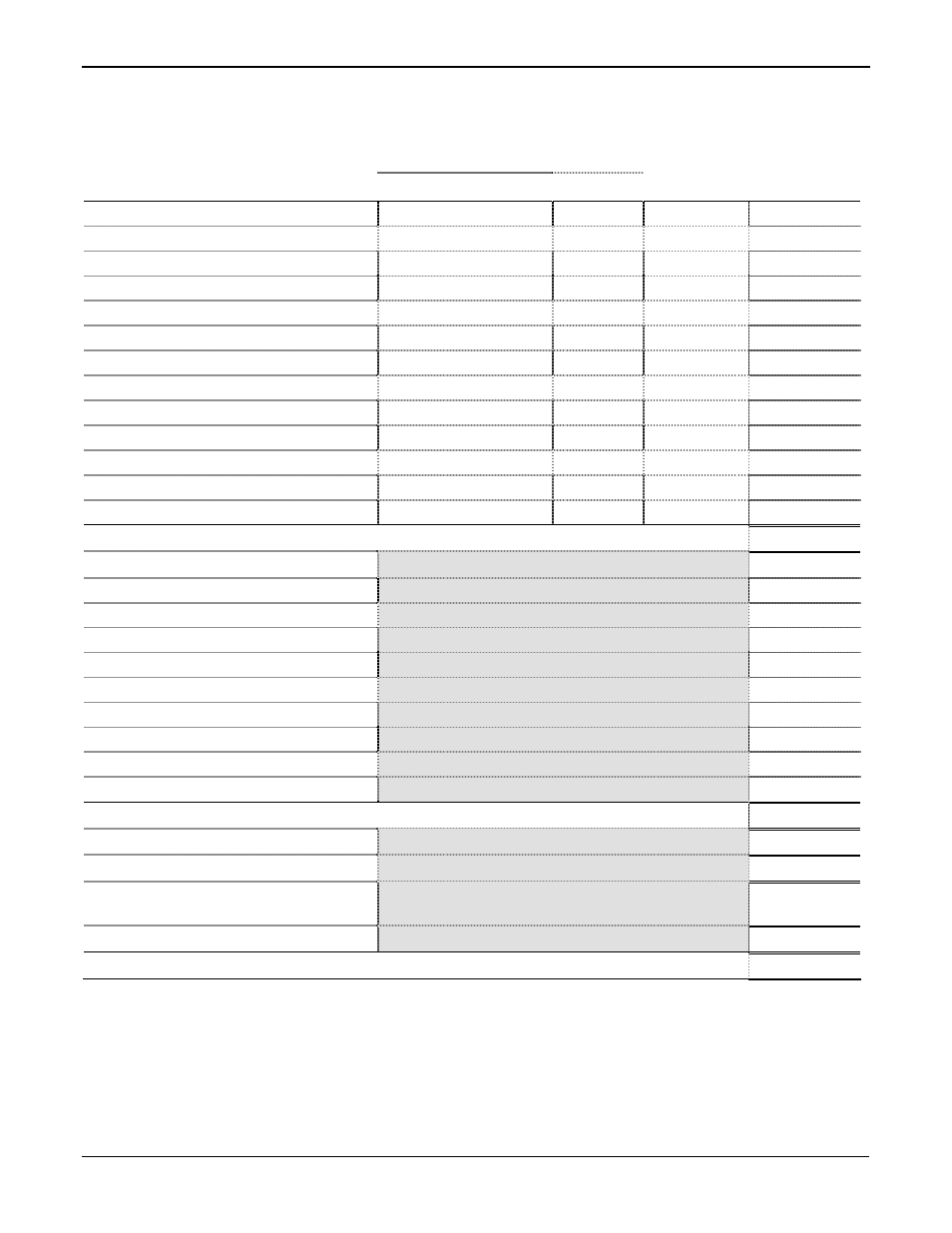
Table 3-5. Estimated Power Consumption
Power Consumption (mW)
Device
Description P
TYPICAL
Quantity
Used
Sub-Total
(mW)
CPU and ROC827 Backplane
Power Input Module PM-12
110 mA @ 12 volts dc
1320 mW
Power Input Module PM-24
55 mA @ 24 volts dc
1320 mW
Per Active LED – Maximum 10
1.5 mA
18 mW
EIA-232 (RS-232) Module
4 mA @ 12 volts dc
48 mW
Per Active LED – Maximum 4
1.5 mA
18 mW
EIA-422/485 (RS-422/485) Module
112 mA @ 12 volts
1344 mW
Per Active LED – Maximum 2
1.5 mA
18 mW
Dial-up Modem Module
95 mA @ 12 volts dc
1140 mW
Per Active LED – Maximum 4
1.5 mA
18 mW
Expanded Backplanes
70 mA @ 12 volts dc
840 mW
35 mA @ 24 volts dc
840 mW
Total for ROC827 Base Unit
mW
AI Modules
Total (from Table 3-6)
AO Modules
Total (from Table 3-7)
DI Modules
Total (from Table 3-8)
DO Modules
Total (from Table 3-9)
DOR Modules
Total (from Table 3-10)
PI Modules
Total (from Table 3-11)
MVS Modules
Total (from Table 3-12)
RTD Modules
Total (from Table 3-13)
Thermocouple Modules
Total (from Table 3-14)
HART Modules
Total (from Table 3-15)
Total for All Modules
mW
Total for ROC827 Base Unit and All Modules
mW
Other Devices
Total (from Table 3-16)
mW
Total for ROC827 Base Unit, All Modules, and
Other Devices
mW
Power System Safety Factor (0.25)
mW
Total for Configured ROC827
mW