Emerson ROC827 User Manual
Page 61
ROC827 Instruction Manual
Issued Mar-06
Power Connections
3-17
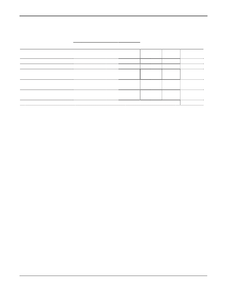
Table 3-11. Power Consumption of the High and Low Speed Pulse Input Modules
Power Consumption (mW)
I/O Module
Description P
TYPICAL
Quantity
Used
Duty
Cycle
Sub-Total
(mW)
PI Module
21 mA @ 12 volts dc No
Channels Active
252 mW
Channel 1
7.4 mA
88.8 mW
Channel 2
7.4 mA
88.8 mW
Per Active LED –
Maximum 4
1.5 mA
18 mW
Jumper set to +T @ 12
volts dc
1.25 * Measured Current
Draw at +T Terminal
Jumper set to +T @ 24
volts dc
2.5 * Measured Current
Draw at +T Terminal
Table Total
Duty Cycle
The duty cycle is the time on divided by the total time, and is
essentially the percent of time that the I/O channel is active
(maximum power consumption).
Duty Cycle = [Active Time * (Signals Duty Cycle)] ÷ (Total Time Period)
For example, if a Pulse Input receives a signal for 6 hours over a 24-hour
time period and the signal’s wave form is on time for 1/3 of the signal’s
period:
Duty Cycle = [6 hours * (1 ч 3)] ч (24 hours) = 0.0825