Galvanic isolation barriers – Eaton Electrical SPI9000 User Manual
Page 47
SPI9000 Inverter Unit FI9 – FI14 User Manual
MN04004002E
For more information visit: www.EatonElectrical.com
4-5
September 2006
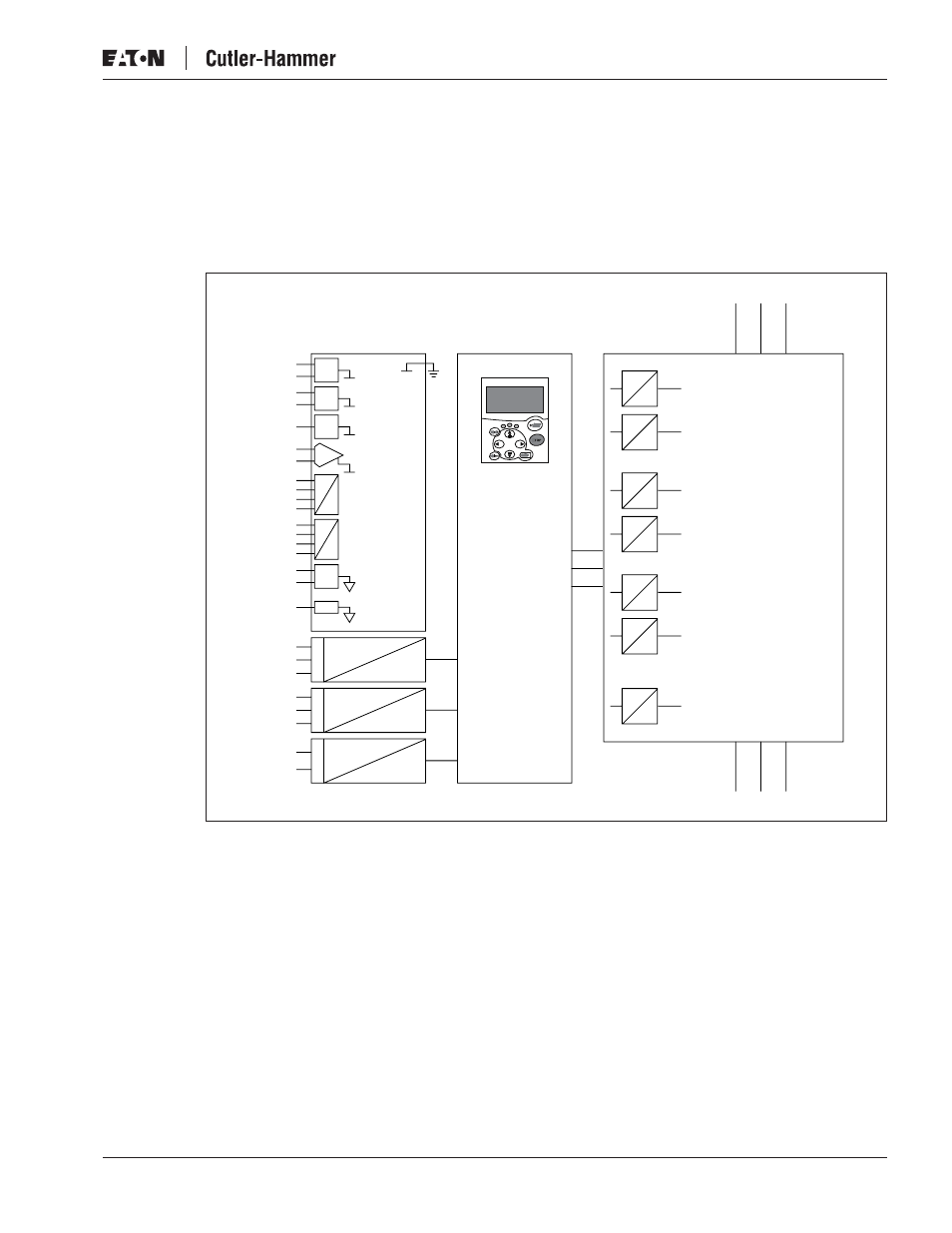
Galvanic Isolation Barriers
The control connections are isolated from the mains potential and the GND terminals are
permanently connected to ground. See Figure 4-8.
The digital inputs are galvanically isolated from the I/O ground. the relay outputs are also
double-isolated from each other at 300V AC (EN-50178).
Figure 4-8: Galvanic Isolation Barriers
RO1/1
Control to
Ground
Digital Input
Group A
Digital Input
Group A
Analog
Output
Digital
Output
RO1/2
RO1/3
RO2/1
RO2/2
RO2/3
TI1+
TI1–
AI1
+10Vref
+24V
GND
GND
AI2+
AI2-
DIN1...
DIN3
CMA
DIN4...
DIN6
CMB
AO1+
AO2-
DO1
Control
Panel
Gate Drivers
Control
Board
Power
Board
U
V
W
L1
L2
L3