Eaton Electrical SPI9000 User Manual
Page 31
SPI9000 Inverter Unit FI9 – FI14 User Manual
MN04004002E
For more information visit: www.EatonElectrical.com
3-7
September 2006
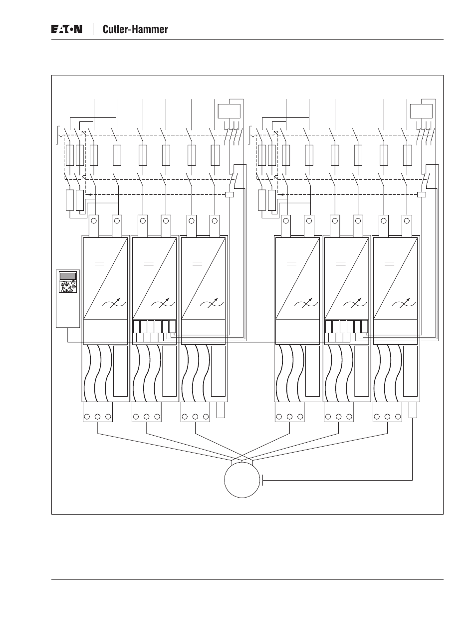
Figure 3-7: FI14 Basic Wiring Diagram with Charging
Controller
Cooli
n
g
Fa
n
X10
H1-7
H903
H900
X9
X15
B+
U
FI 10 Module U
B–
Cooli
n
g
Fa
n
DC+
DC–
DC+
DC–
B+
V
FI 10 Module V
B–
DC+
DC–
Cooli
n
g
Fa
n
B+
W
PE
FI 10 Module W
B–
External
Supply
Note: Min. Cable Length
(131.2’) 40m
Cooli
n
g
Fa
n
X10
H1-7
H903
H900
X9
X15
B+
U
FI 10 Module U
B–
M
Cooli
n
g
Fa
n
DC+
DC–
DC+
DC–
B+
V
FI 10 Module V
B–
DC+
DC–
Cooli
n
g
Fa
n
B+
W
PE
FI 10 Module W
B–
External
Supply