Power connections – Eaton Electrical SPI9000 User Manual
Page 33
SPI9000 Inverter Unit FI9 – FI14 User Manual
MN04004002E
For more information visit: www.EatonElectrical.com
3-9
September 2006
Power Connections
DC Supply and Motor Cables
The power cables are connected to terminals DC+ and DC- (R+/B+ and DC terminals when
using an external charging circuit) and the motor cables to terminals U, V and W. A cable
entry gland should be used at the motor cable end to reach the EMC levels, see Table 3-2.
Use cables with a heat resistance of at least +60C. The cables and the fuses must be sized
according to the inverter nominal output current which you can find on the rating plate.
Installation of cables according to UL regulations is presented on Page 3-17 and aR fuse sizes
in Tables 3-2 and 3-3 below.
If the motor temperature protection of the drive is used as an overload protection, the cable
shall be chosen accordingly. If three or more cables are used in parallel for bigger units, each
cable requires a separate overload protection.
These instructions apply only to installations with one motor and one cable connection from
the inverter to the motor. In any other case, ask the factory for more information.
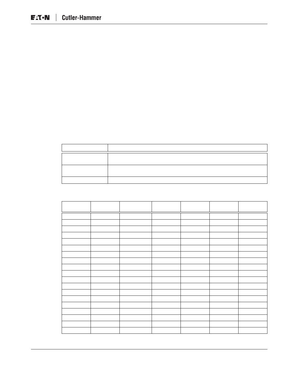
Table 3-1: Cable Types Required to Meet Standards
Fuses, 465 – 800V DC Inverters
Table 3-2: Fuses Used in 465 – 800V DC Inverters
Cable Type
EMC Level T
Supply Cable
Power cable intended for fixed installation and the specific DC voltage.
Shielded cable not required.
Motor Cable
Power cable equipped with concentric protection wire and intended for the
specific mains voltage.
Control Cable
Screened cable equipped with compact low-impedance shield.
Nominal
Current
Frame
Bussman aR
Fuse Type
Fuse Size
Fuse U
n
(V)
Fuse I
n
(A)
No. of Fuses
140
FI9
170M3819
DIN1
690
400
2
170
FI9
170M3819
DIN1
690
400
2
205
FI9
170M6812
DIN3
690
800
2
245
FI9
170M6812
DIN3
690
800
2
300
FI10
170M8547
3SHT
690
1250
2
385
FI10
170M8547
3SHT
690
1250
2
460
FI10
170M8547
3SHT
690
1250
2
520
FI12
170M8547
3SHT
690
1250
4
590
FI12
170M8547
3SHT
690
1250
4
650
FI12
170M8547
3SHT
690
1250
4
730
FI12
170M8547
3SHT
690
1250
4
820
FI12
170M8547
3SHT
690
1250
4
920
FI12
170M8547
3SHT
690
1250
4
1030
FI13
170M8547
3SHT
690
1250
6
1150
FI13
170M8547
3SHT
690
1250
6
1300
FI13
170M8547
3SHT
690
1250
6
1600
FI14
170M8547
3SHT
690
1250
2 x 6
1940
FI14
170M8547
3SHT
690
1250
2 x 6
2300
FI14
170M8547
3SHT
690
1250
2 x 6