Chapter 2 • hardware installation 2-15 – Extron Electronics Matrix 200 User Manual
Page 31
Extron • Matrix 200 • User’s Manual
Chapter 2 • Hardware Installation
2-15
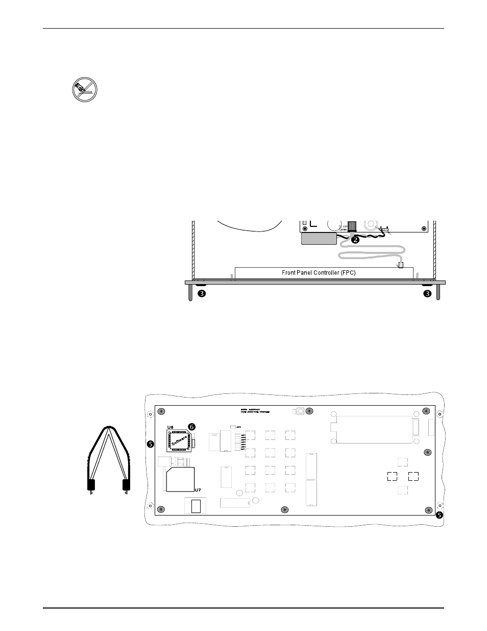
Installing FPC/QS-FPC Software Update
1. If the FPC/QS-FPC is mounted on the Matrix 200, refer to the procedure on
page 2-2 to open the cabinet and then continue with step 2.
___________ Electro-Static Discharge (ESD) can damage IC chips, even when it is not
enough to be humanly detected (felt, heard or seen). Do NOT touch IC chips
without being electrically grounded.
2. With the top cover off the Matrix, unplug the cable that connects the FPC/QS-
FPC to the Main Controller board and put it aside.
3. Remove the four (4) screws that hold the FPC/QS-FPC to the Matrix cabinet.
4. Place the FPC/QS-FPC face down on a clean workspace. If necessary, place
it on a soft pad to prevent damage.
5. Using a 1/4" nut driver, remove four (4) 1/4" nuts that hold the cover on the
back of the FPC/QS-FPC.
6. After first properly grounding yourself, use the PLCC IC puller to remove the
old Software chip. Squeeze the tool to align the hooks with the slots provided
in opposite corners of chip socket U8. Insert the hooks, squeeze gently and
pull the IC straight out of the socket. Set the chip aside.
7. Note the orientation of the angled corner of the new Software chip. Position
this to match the angled corner of the socket and carefully press it in place.
8. Reinstall the cover on the back of the FPC/QS-FPC and reverse the above
procedure to put the Matrix back in place.
Red
Black
PLCC Chip Puller