Extron Electronics Matrix 200 User Manual
Page 13
Extron • Matrix 200 • User’s Manual
Chapter 1 • Introduction to the Matrix 200
1-5
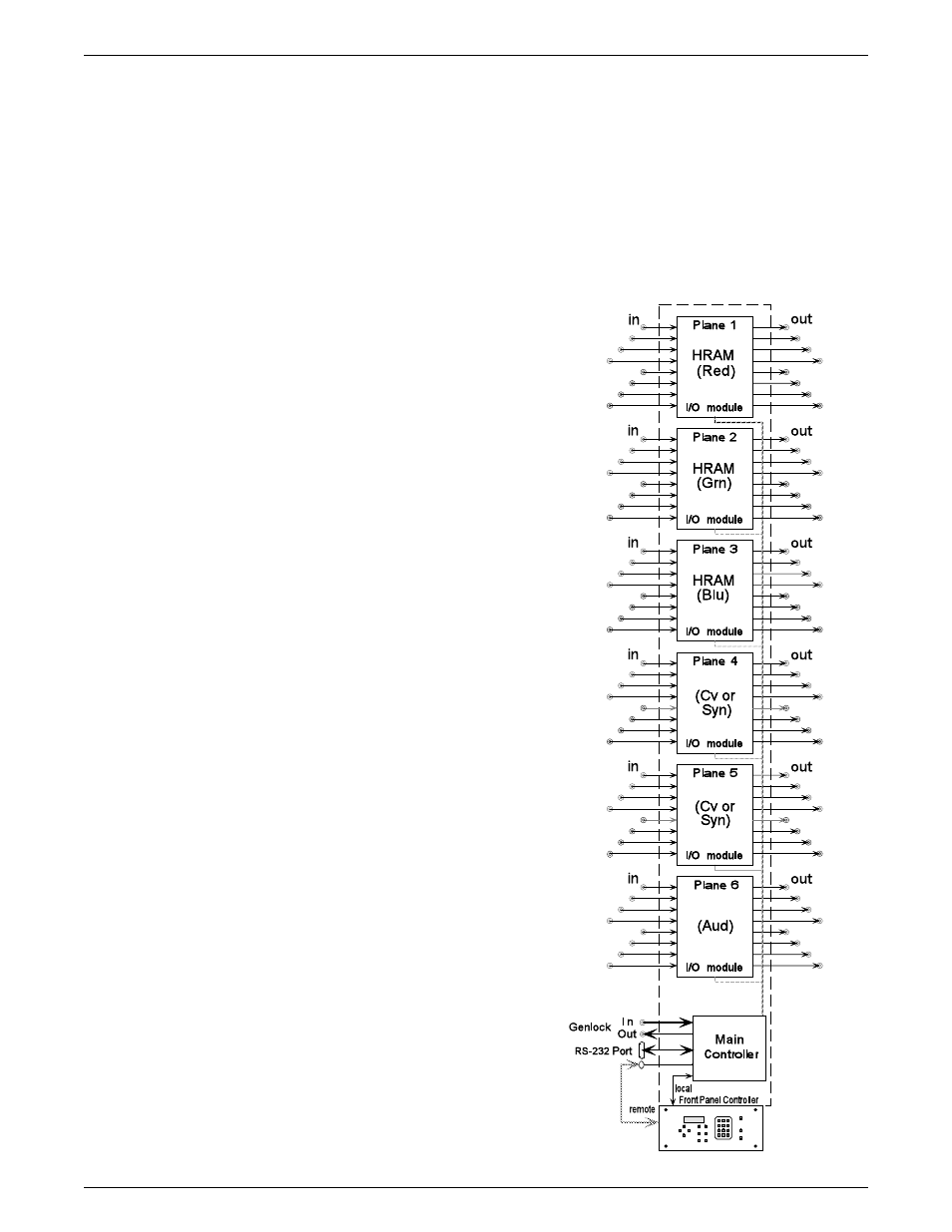
Sample Configuration
The picture here shows one example of the I/O modules that could be installed in
six planes of a Matrix 200. See page 1-1 for I/O modules and possible
configurations.
For example, an 8 x 8 RGBS switcher requires: three 8 x 8 high-resolution
analog modules (HRAM) and one 8 x 8 sync module (Syn). This would occupy
the Red, Green, Blue and one Sync/Video planes. The fifth plane could have a
composite video module (Cv), and the sixth plane could have an audio switching
module (Aud).
This configuration is capable of being
controlled and routed as three
separate switchers:
• one 8 x 8 RGBS matrix switcher
• one 8 x 8 video switcher
• one 8 x 8 audio switcher
In addition, SmartControl™ allows
the Matrix 200 to group these
functions as a single RGBS
composite video switcher with stereo
audio.
The bottom of the diagram illustrates
how the Main Controller (and the
optional Front Panel Controller)
routes the various inputs to the
outputs.