Chapter 2 • hardware installation 2-13, Installing i/o modules in the rear panel, Extron • matrix 200 • user’s manual – Extron Electronics Matrix 200 User Manual
Page 29
Extron • Matrix 200 • User’s Manual
Chapter 2 • Hardware Installation
2-13
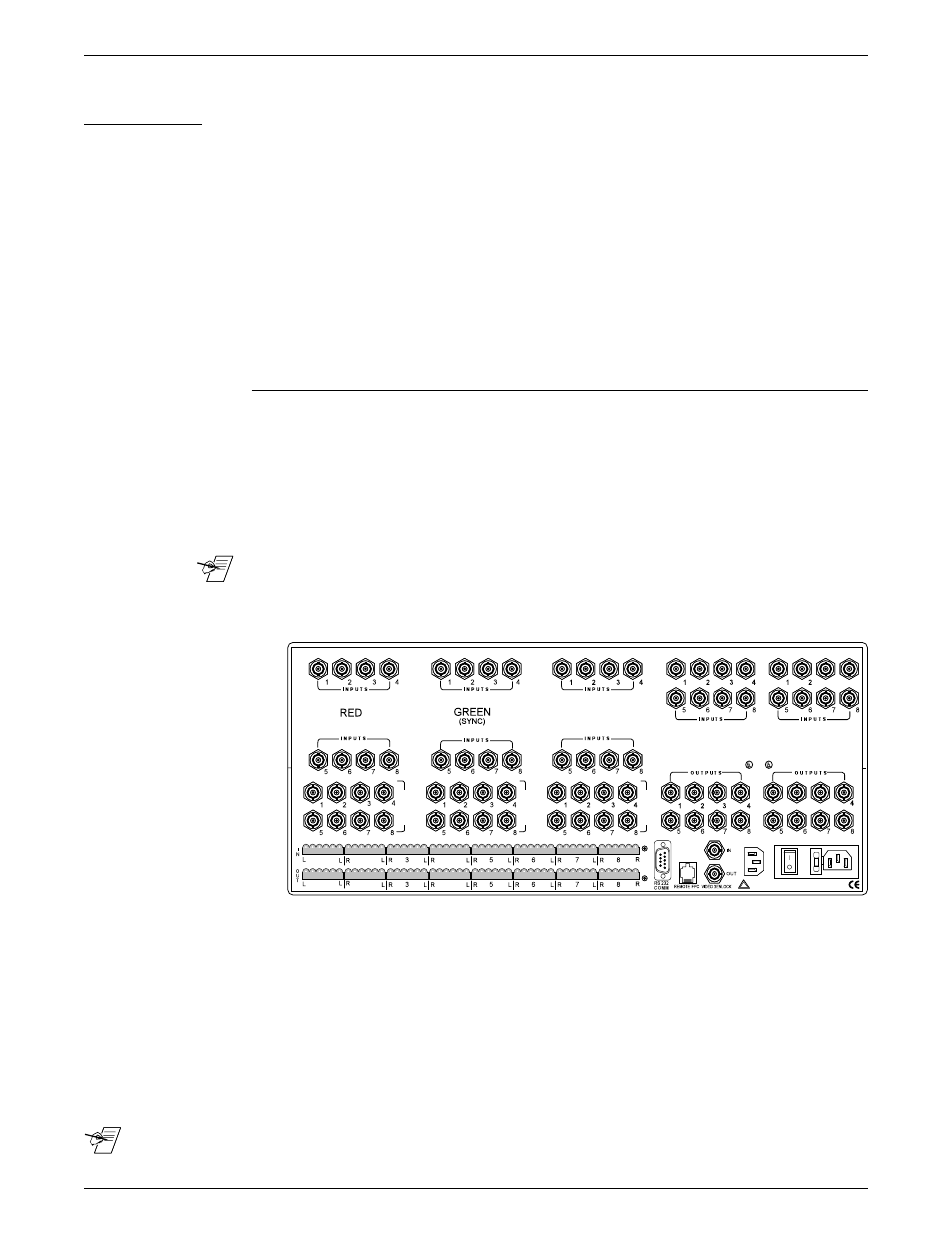
Installing I/O Modules in the Rear Panel
There are three types of modules that can be installed in the rear panel of the
Matrix 200: HRAM module, for RGB; Sync module, for Horizontal and/or Vertical
Sync; and Composite Video module for Composite Video or S-Video. Positions,
or “planes” 1, 2, and 3 will accommodate only HRAM modules. Planes 4 and 5
will accommodate either Sync or Composite video modules, but not HRAM. A
Matrix unit cannot have one or two HRAM modules; it must have three (for red,
green and blue) or none.
Use this procedure to install any HRAM, Sync or Composite Video module.
Locate the position on the back panel for the new module. An HRAM can only be
installed in the locations marked Red, Blue or Green. A Sync module or a
Composite Video module can only be mounted in the positions marked as such.
If there is one sync module, it must be in the first position after the Blue, or
Plane 4.
Configuration plane 1
plane 2
plane 3
plane 4
plane 5
RGsB
HRAM
HRAM
HRAM
-
-
RGBS
HRAM
HRAM
HRAM
Sync
-
RGBHV
HRAM
HRAM
HRAM
Sync
Sync
RGBSCv
HRAM
HRAM
HRAM
Sync
C-Video
1 Cv
-
-
-
C-Video
-
2 Cv or 1 YC
-
-
-
C-Video
C-Video
Audio can be included with any of these combinations.
_______ Address switches are set according to the physical location.
The illustration here shows the modules already installed.
1. Remove the Matrix top cover (procedure on page 2-2).
2. Locate the gray ribbon cables that connect the Main Controller board to the
existing I/O modules and determine where the new module will be connected.
If cables from adjacent modules are in the way, they may be unplugged and
reconnected later.
3. On the rear panel, remove the 16 round plastic plugs that cover the holes
where the new module will be installed.
4. On the new module, remove the nuts from the 16 BNC connectors.
______ If installing both a Sync module and a Composite Video module, the Sync module must be in
Plane 4 and the Composite Video in Plane 5.
Tools for Installation:
3/16" flat screwdriver
#4 Phillips screwdriver
#6 Phillips screwdriver
9/16" Socket/nutdriver
1
2
3
4
3
BLUE
O
O
U
U
TT
P
P
U
U
TT
S
S
O
O
U
U
TT
P
P
U
U
TT
S
S
O
O
U
U
TT
P
P
U
U
TT
S
S
SYNC/
VIDEO
SYNC/
VIDEO
1
1
2
2
4
4
LISTED
1T23
ITE
c
REDUNDANT POWER
FUSE: 250V ~0.8A TT
AC POWER INPUT
100-240V ~0.5A MAX 50/60 Hz
DISCONNECT ALL POWER CORDS BEFORE SERVICING
!