Chapter 2 • hardware installation 2-11 – Extron Electronics Matrix 200 User Manual
Page 27
Extron • Matrix 200 • User’s Manual
Chapter 2 • Hardware Installation
2-11
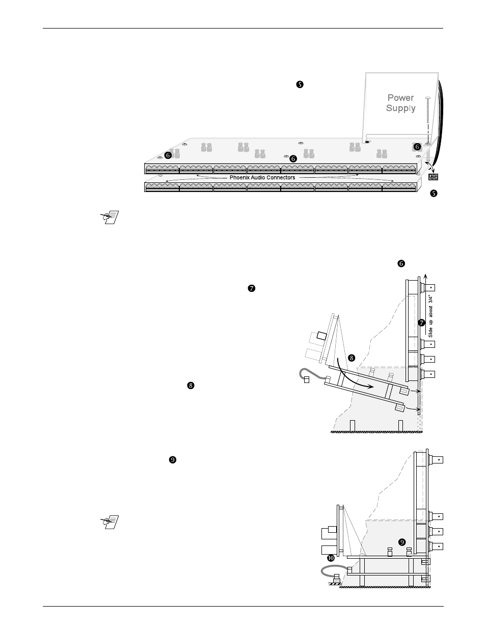
5. Unpack the Audio Matrix module and locate the following:
· The bracketed attachment is the power supply.
· Two rows of female Phoenix audio connectors,
eight in each row. Six pins per connector.
· Board address DIP switches. (See
at right.)
· 3-inch ribbon cable attached. (Not visible in the
picture to the right.)
_______ The address DIP switches are factory-set. See right end of picture above. They
should be set to represent an address of five (0101 binary).
6. Remove the six nuts from the screws that hold the two boards together. Set
the screws and washers aside; the nuts will not be needed. (See
above.)
7. Slide the rear panel upward about 3/4", while keeping it in the
cabinet grooves. (See
right.)
8. Orient the Audio Module above the nylon
spacers, with the audio connector
strips to the rear. Tilt the module
slightly and slip the audio connectors
through the parallel openings in the
rear panel and lower it to a
horizontal position.
(See
right.)
9. While holding the Audio Module in position
with the rear panel, lower them both
carefully until the module rests on the six nylon spacers. (See
below.)
10. With the Audio Module loosely in position, lift the corner by
the power supply slightly and plug the ribbon cable
into the nearest slot (J4) on the Main
Controller board.
_______ The I/O connectors on the Main Controller
board are on a parallel bus, therefore it
doesn't matter which module is plugged to
which connector. Because of its cable length,
the Audio Board must plug into the closest
connector.