Power, Installation, cont’d – Extron Electronics MAV Plus Series User Manual
Page 41
Installation, cont’d
CrossPoint 450 Plus and MAV Plus Switchers • Installation
2-18
Extron
BBG 6 A
Black Burst/Color Bar/
Audio Generator
50/6
0 Hz
100-24
0V
0.3A
R
/R-Y
R
/R-Y
I
N
P
U
T
S
O
U
T
P
U
T
S
G
/Y
2
RGB/R-Y
, B-Y,
Y
RGB
1
G-Y
B
/B-Y
B
/B-Y
H
/HV
H
/HV
V
V
VIDEO
S-VI
DEO
D1
R/R-Y
G/Y
B/B-Y
H/H-Y
RS-232
/422
G
E
N
L
O
C
K
V
IN
OUT
Video Camera
Video Camera
Video Camera
Monitor
VCR
Extron
MAV Plus AV 3232
Matrix Switcher
I
N
P
U
T
S
ANAHEIM,
CA
100-240V
5
0/6
0Hz
1.2A MAX.
1
5
9
13
17
21
25
29
30
26
22
18
14
10
6
2
3
7
11
15
19
23
27
31
32
28
24
20
16
12
8
4
O
U
T
P
U
T
S
1
5
9
13
17
21
25
29
30
26
22
18
14
10
6
2
3
7
11
15
19
23
27
31
32
28
24
20
16
12
8
4
EXT
SYNC
ETHERNET
REMO
TE
RS-232/RS-422
LINK
AC
T
L
1
R
L
2
R
L
3
R
L
4
R
L
5
R
L
6
R
L
7
R
L
8
R
L
9
R
L
10
R
L
11
R
L
12
R
L
13
R
L
14
R
L
15
R
L
16
R
L
17
R
L
18
R
L
19
R
L
20
R
L
21
R
L
22
R
L
23
R
L
24
R
L
25
R
L
26
R
L
27
R
L
28
R
L
29
R
L
30
R
L
31
R
L
32
R
I
N
P
U
T
S
I
N
P
U
T
S
ANAHEIM,
CA
100-240V 5
0/60Hz
1.2A MAX.
1
5
9
13
17
21
25
29
30
26
22
18
14
10
6
2
3
7
11
15
19
23
27
31
32
28
24
20
16
12
8
4
O
U
T
P
U
T
S
L
1
R
L
2
R
L
3
R
L
4
R
L
5
R
L
6
R
L
7
R
L
8
R
L
9
R
L
10
R
L
11
R
L
12
R
L
13
R
L
14
R
L
15
R
L
16
R
L
17
R
L
18
R
L
19
R
L
20
R
L
21
R
L
22
R
L
23
R
L
24
R
L
25
R
L
26
R
L
27
R
L
28
R
L
29
R
L
30
R
L
31
R
L
32
R
O
U
T
P
U
T
S
1
5
9
13
17
21
25
29
30
26
22
18
14
10
6
2
3
7
11
15
19
23
27
31
32
28
24
20
16
12
8
4
EXT
SYN
C
ETHERNET
REMO
TE
RS-232/RS-422
LINK
AC
T
VGA Input
Extron
VSC 900D
Computer-to-Video
Scan Converter
DISTRIB
UTION AMPLIFIE
R
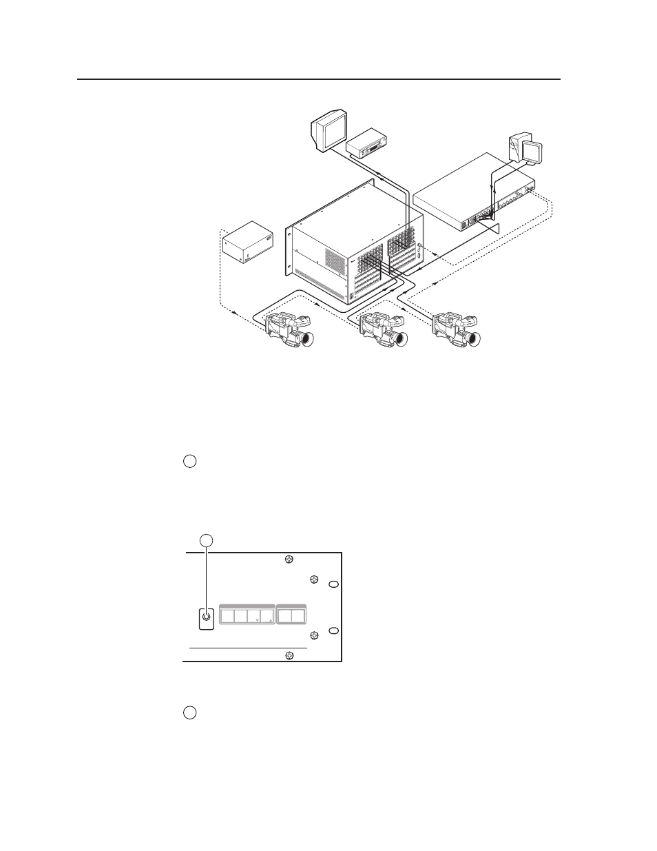
Figure 2-22 — Multiple device external sync connection example
If no external sync timing source is connected to the switcher, switching occurs
immediately.
Power
12
AC power connector —
Plug a standard IEC power cord into this connector
to connect the switcher to a 100 VAC to 240 VAC, 50 or 60 Hz power source.
Front Panel Configuration Port
(Matrix Sizes up to 1616 Only)
AUDIO
VIDEO
I/O
CONTROL
ENTER
PRESET
VIEW
ESC
CROSSPOINT 450 PLUS SERIES
ULTRA-WIDEBAND MATRIX SWITCHER
WITH
ADSP™
AND
IP LINK™
CONFIG
13
Figure 2-23 — Front panel configuration port
13
Configuration port
— This 2.5 mm mini stereo jack serves the same serial
communications function as the rear panel Remote port, but it is easier to
access than the rear port after the matrix switcher has been installed and
cabled. The optional 9-pin D to 2.5 mm mini jack TRS RS-232 cable,
part #70-335-01 (figure 2-24), can be used for this connection.