0 external enclosures, 1 power connection, Figure 9 nic-encl1 internal view – Emerson MONITORING OpenComms User Manual
Page 39: 2 communication connection, Xternal, Nclosures, Power connection, Communication connection, Figure 9, Nic-encl1 internal view
External Enclosures
33
8.0
E
XTERNAL
E
NCLOSURES
8.1
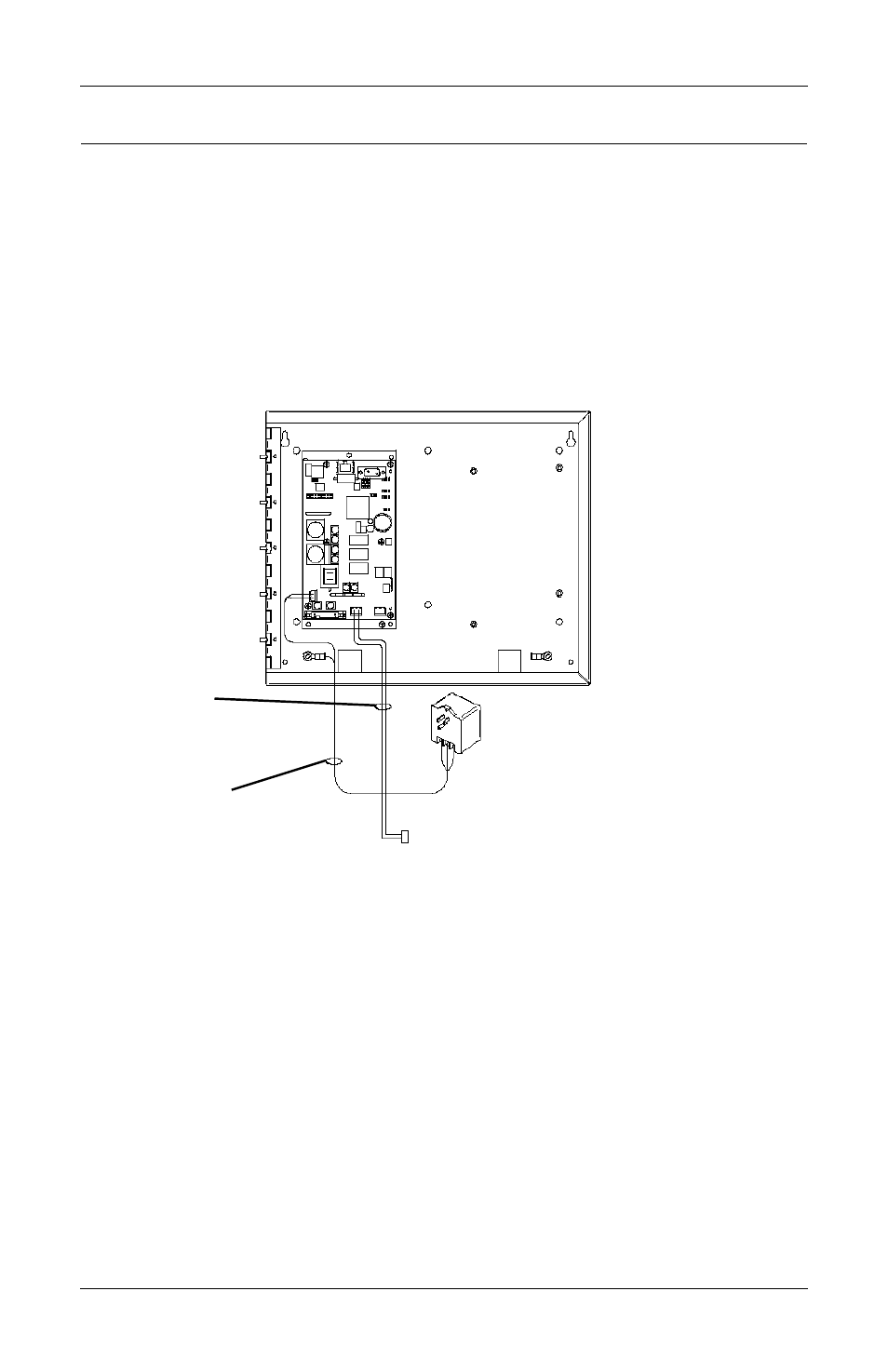
Power Connection
Power for the OpenComms Network card should be sourced from the
supplied wall-plug transformer. Use field-supplied wiring to connect
the outer terminals on the transformer to the screw connectors at TB3
on the Network Interface card. A field-supplied ground wire attaches
to the center terminal on the transformer and connects to the ground-
ing stud in the lower corner of the enclosure.
Figure 9
NIC-ENCL1 internal view
8.2
Communication Connection
Communications to the OpenComm Network Card is generally estab-
lished by using the unit’s SiteScan interface port. The specifics on
location and wiring details can be found in the respective unit’s user
manual.
The unit’s communications port is EIA-422, which measures ~3-5VDC
between the positive and negative terminals. The connection is polar-
ity sensitive, so use a voltmeter to verify polarity. The connection is
positive-to-positive and, negative-tonegative-. The result when the
card and the unit are connected together, a voltmeter will measure ~
3-5 VDC. Once proper communication has been established, voltage
readings will fluctuate.
To SiteScan
connection
terminals on unit
Field-supplied
use 18AWG
Refer to specific unit installation
communication connection