8 diagnostics, Figure 5 led locations, Diagnostics – Emerson MONITORING OpenComms User Manual
Page 24: Figure 5, Led locations
Operation
18
4.8
Diagnostics
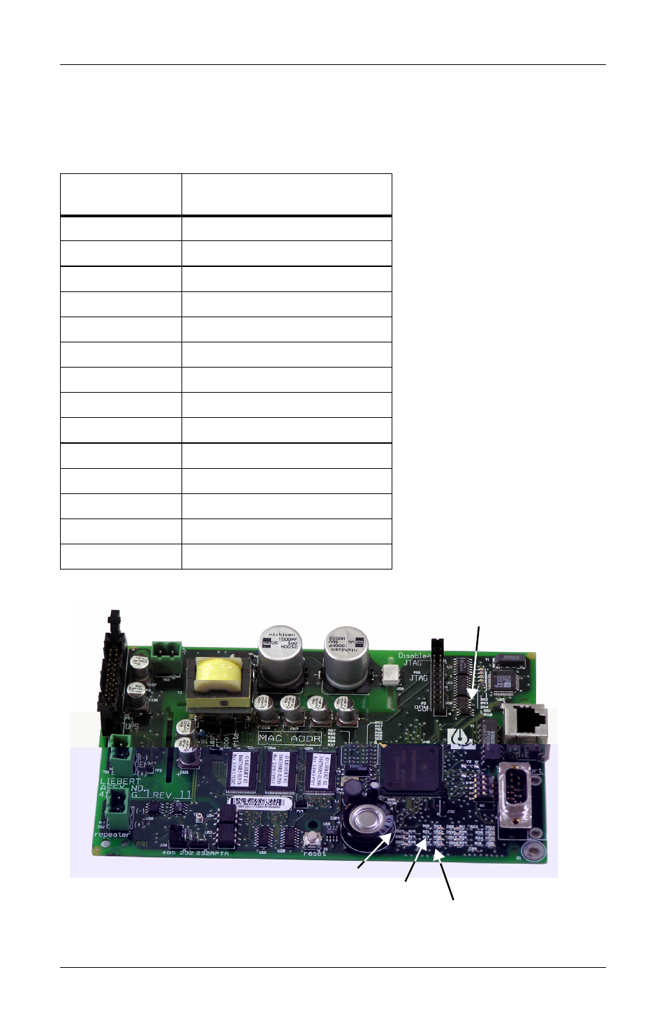
A number of LEDs are provided on the interface card to provide infor-
mation for diagnostic purposes. The following table summarizes their
indications:
Figure 5
LED locations
LED
Identifier
Description
DS1
Ethernet Port Collision
DS2
Ethernet Port Receive
DS3
Ethernet Port Transmit
DS4
Ethernet Port Link
DS5
Not used
DS6
Not used
DS7
Repeater Port Receive
DS8
IGM Port Receive
DS9
Microprocessor in Operation
DS10
Serial Port Receive
DS11
Serial Port Transmit
DS12
Repeater Port Transmit
DS13
IGM Port Transmit
DS14-19
Not used
DS9
DS13
DS8
DS8