Magnum Energy MP Extension Box (MPX Series) User Manual
Page 38
3.0 Installation
© 2011 Magnum Energy, Inc.
34
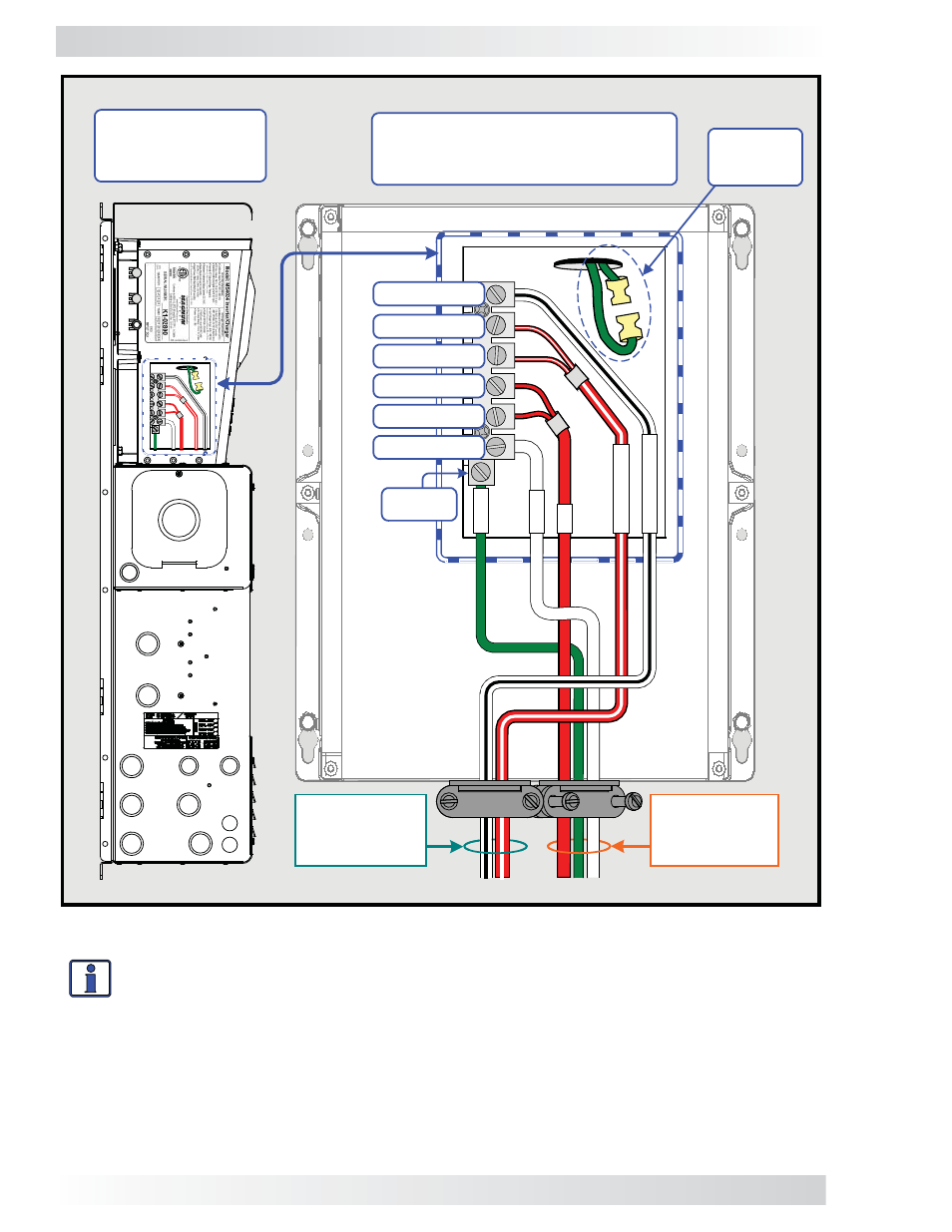
MS4024 Series Inverter (LEG 2) –
showing AC wires from the
internal AC wiring terminal
30
Left side view of
inverter mounted
on MPX Enclosure
Inverter AC
Input Wires
(Leg 2 Only)
Inverter AC
Output Wires
(Leg 2 Only)
AC
GROUND
.
AC HOT 2 OUT
.
AC NEUT IN
.
AC NEUT OUT
.
AC HOT 1 OUT
.
AC HOT 1 IN
.
AC HOT 2 IN
.
RED
.
WHI
T
E
.
RED w/
STRI
PE
.
W
H
IT
E w/
STRI
PE
.
GREEN
See NOTE
below
Info: When wiring the MS4024 (or any other MS Series inverter), both the inverter input
and output neutral wires must be connected to a AC NEUTRAL busbar inside the MP en-
closure. This is because — depending on the inverter’s operating mode — the inverter’s
input and output neutral terminals may not be connected together (i.e., inverter’s neu-
trals are not connected when “inverting”, and are combined when “charging”).
NOTE: Because a neutral to ground connection is also made in the MP enclosure, the neutral to
ground connection inside the MS4024 must be disconnected. Refer to your MS4024 owner’s manual
for information on how this is done.
Figure 3-20a, Inverter AC Input and Output Wiring Diagram