Magnum Energy MP Extension Box (MPX Series) User Manual
Page 17
3.0 Installation
© 2011 Magnum Energy, Inc.
13
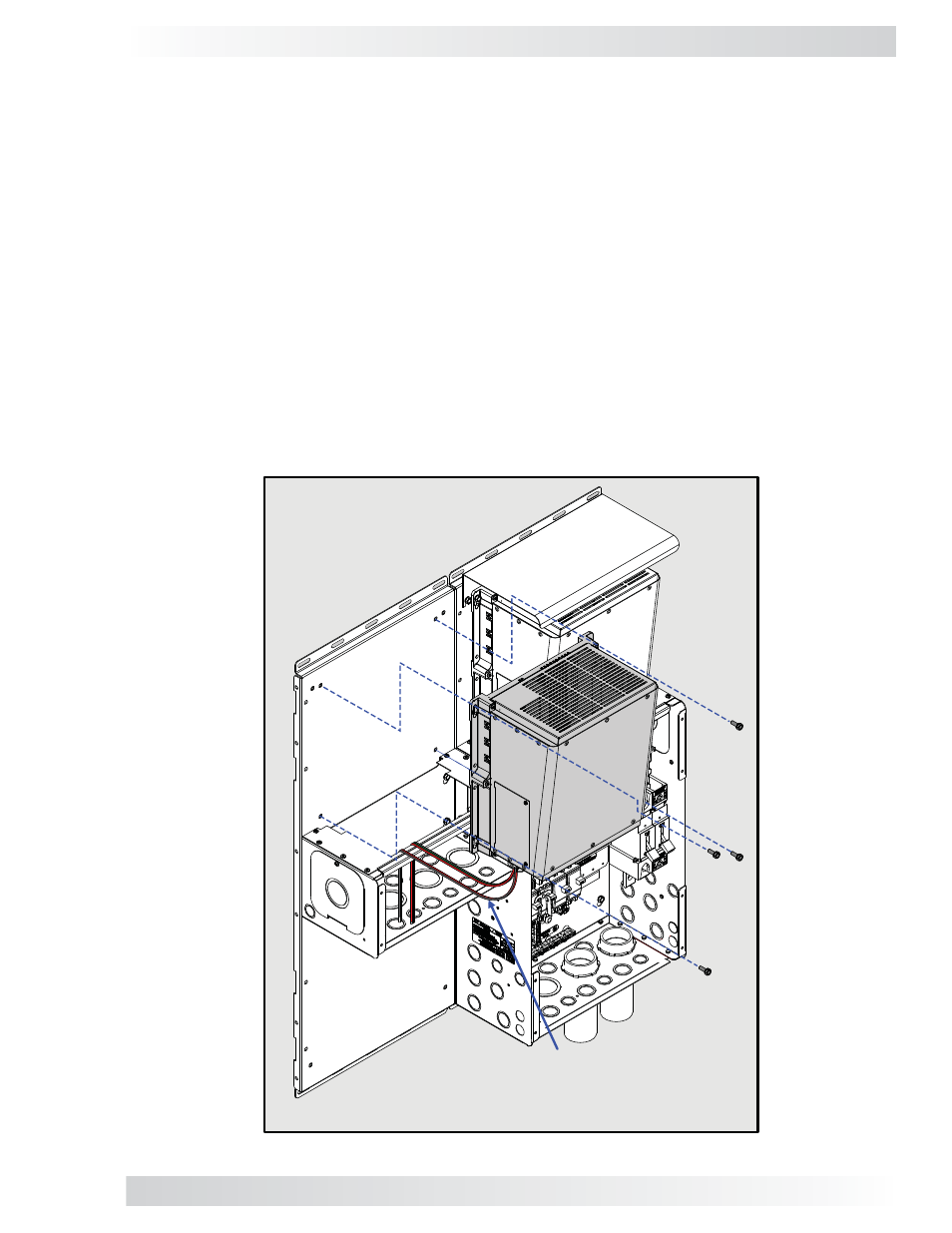
Figure 3-11, Mounting the Second Inverter on the MPX
The additional inverter fi ts on top the MPX and is secured to the backplate/wall (Figures 3-11 & 3-12).
Note: Before mounting, pull the unconnected ends of the AC wiring outside of the inverter and
through the MPX enclosure (see Figure 3-12).
1. Place the Magnum inverter on top of the MPX.
2. Secure it to the backplate/wall using four Hex head bolts and the inverter’s keyhole slots.
3. Tighten the Hex head bolts to secure the inverter to the backplate/wall.
3.1.5 Connect and Separate Inverter AC Wires
Prior to mounting the second inverter on the MP enclosure, connect the AC wires provided in the
MPX AC wire kit (see Figure 2-1, Item F and Table 2-1) to the inverter’s AC wiring terminal (see
the inverter owner’s manual or the MP Owner’s Manual for guidance in connecting the AC wires
inside the inverter). Before connecting the AC wires, separate them into two wire bundles (inverter
AC input and inverter AC output) to help ensure they are connected correctly after the inverter is
mounted on the MP enclosure.
It is possible to connect these wires after the inverter is mounted. However, you have more space and
easier access to the wiring terminal when the inverter’s AC wires are connected before mounting –
especially when installing multiple inverters side-by-side on an MP enclosure system. Replace the
AC wiring access plate once you have connected the wires inside the inverter.
3.1.6 Mounting the Second Inverter onto the MPX
Note:
Prior to mounting, connect the AC input
and output wires within the new inverter (refer
to your inverters owner’s manual), and then
route the wiring through the MPX.