0 installation, Figure 3-17, dc cable connections – Magnum Energy MP Extension Box (MPX Series) User Manual
Page 23
3.0 Installation
© 2011 Magnum Energy, Inc.
19
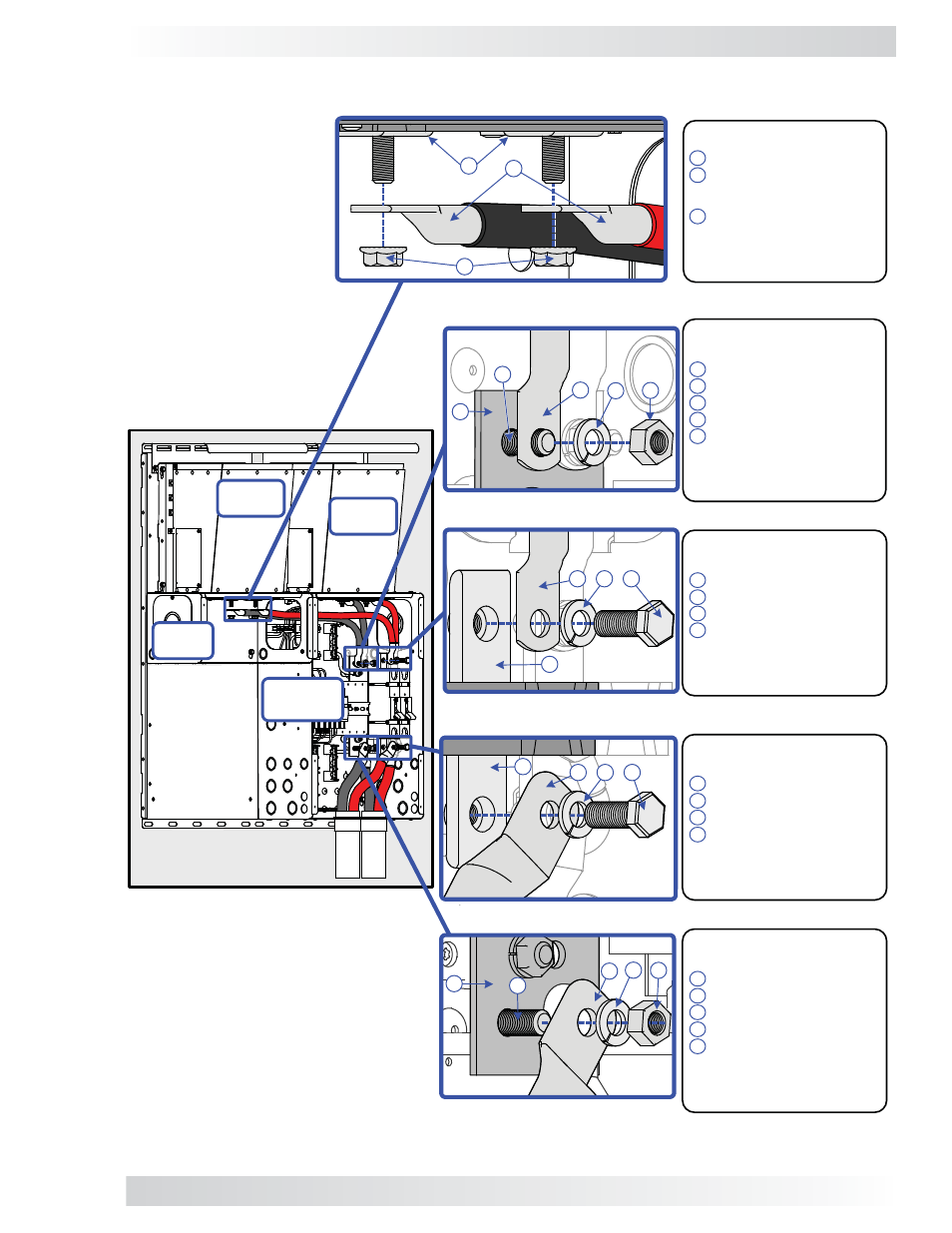
Inverter Hardware Stack-up:
Inverter DC terminals
Inverter cable lugs
[(-) to shunt busbar,
(+) to inverter DC breaker]
5/16-18 nut (Flange or Kep)
DO NOT place anything
between the inverter DC
terminals and the inverter
cable lugs.
1
2
3
Top of Shunt Busbar Hardware
Stack-up:
DC shunt busbar (top)
Hex bolt (3/8-16-3/4")
Negative (-) battery cable lug
Split-lock washer
3/8-16 nut
DO NOT place anything
between the DC shunt busbar
and the negative inverter cable
lug.
1
2
3
4
5
Top of DC Breaker Hardware
Stack-up:
DC breaker (top) terminal
Positive (+) inverter cable lug
Split-lock washer
Hex bolt (3/8-16-3/4")
DO NOT place anything
between the DC breaker
terminal and the positive
inverter cable lug.
1
2
3
4
Bottom of DC Breaker Hardware
Stack-up:
DC breaker (bottom) terminal
Positive (+) battery cable lug
Split-lock washer
Hex bolt (3/8-16-3/4")
DO NOT place anything
between the DC breaker
terminal and the positive
battery cable lug.
Bottom of Shunt Busbar
Hardware Stack-up:
DC shunt busbar (bottom)
Hex bolt (3/8-16-3/4")
Negative (-) battery cable lug
Split-lock washer
3/8-16 nut
DO NOT place anything
between the DC shunt busbar
and the negative battery cable
lug.
1
2
3
4
4
3
2
1
5
3
1
2
3
4
5
2
1
2
1
3 4
2
1
3 4
1
3 4 5
2
MPX
MP
Enclosure
Inverter
#2
Inverter
#1
Figure 3-17, DC Cable Connections
I
NVERTER
DC N
EGATIVE
AND
P
OSITIVE
C
ONNECTIONS
I
NVERTER
N
EGATIVE
TO
S
HUNT
B
USBAR
(T
OP
) DC P
OSITIVE
C
ONNECTION
I
NVERTER
P
OSITIVE
TO
I
NVERTER
DC B
REAKER
(T
OP
) C
ONNECTION
B
ATTERY
P
OSITIVE
TO
I
NVERTER
DC B
REAKER
(B
OTTOM
) C
ONNECTION
B
ATTERY
N
EGATIVE
TO
S
HUNT
B
USBAR
(B
OTTOM
) C
ONNECTION