2 wiring the mpx – Magnum Energy MP Extension Box (MPX Series) User Manual
Page 21
3.0 Installation
© 2011 Magnum Energy, Inc.
17
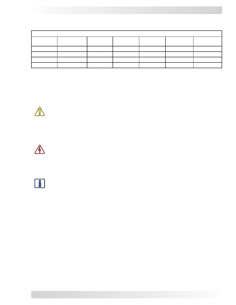
3.2 Wiring the MPX
This section covers installing AC, DC, and communication wiring for each MPX model (Table 3-1).
TABLE 3-1, MPX WIRING TABLE
MPX Model
MP Enclosure
Used With:
Inverter
AC Wiring
External*
AC Wiring
Inverter
DC Wiring
Battery Bank
DC Wiring
Communica-
tions Wiring
MPXS-30D
MPSL-30D
Figure 3-18a
Figure 3-18b
Figure 3-18c
Figure 3-18d
Figure 3-18e
MPXS-30D
MPSH-30D
Figure 3-19a
Figure 3-19b
Figure 3-19c
Figure 3-19d
Figure 3-19e
MPXS-60S
MPSL-60S
Figure 3-21a
Figure 3-21b
Figure 3-21c
Figure 3-21d
Figure 3-21e
MPXD-30D
MPDH-30D
Figure 3-22a
Figure 3-22b
Figure 3-22c
Figure 3-22d
Figure 3-22e
*- ‘External’ refers to wiring that is required outside the MP/MPX panel (i.e., wiring to loads, grid/gen input wiring)
3.2.1 Wiring Guidelines
This section provides general information on the AC wiring to/from the new inverter, from the incom-
ing AC source, and to the outgoing AC distribution panel (i.e., inverter sub-panel).
IMPORTANT: All wiring should meet local codes and standards and be performed by quali-
fi ed personnel such as a licensed electrician.
CAUTION: Before installing any AC wiring, review all safety information in the MP Owner’s
Manual (PN: 64-0028) and at the beginning of this manual, and the information below
to ensure a safe system:
• The AC wires must be appropriately sized, and must be no less than #10 AWG (5.3
mm
2
) gauge copper wire and be approved for residential wiring.
• DO
NOT connect the Magnum inverter’s output to an AC power source. This could
cause severe damage to the inverter and is not covered under warranty.
WARNING: To reduce the risk of fi re, do not connect a 120V AC only inverter to both
busbars in an AC load center (circuit breaker panel) having multi-wire branch circuits
connected. Every circuit connected to a 120V AC panel must have its own neutral; other-
wise, currents on shared neutrals will add rather than subtract – overloading the neutral
conductor.
The AC and DC wires into and out of the MP enclosure and the MPX extension must be protected as re-
quired by code. This can be done by using jacketed wires or by feeding wires through conduit.
Info: If using a Magnum inverter, and the AC wires are individual conductors (i.e., not
jacketed), the strain reliefs on the inverter can be replaced with 3/4” grommets.
• Use proper clamps or other approved methods for securing the cable/conduit to the enclosure.
• The MP enclosure is specifi cally approved/designed for both AC and DC wiring. However, where
DC wiring must cross AC or vice-versa, try to make the wires at the crossing point 90° to one
another.
• Use only copper wires with a minimum rating of 150V, 75°C if only 120V AC power is being used;
or, with a minimum rating of 300V, 75°C if 120/240V AC power is being used.
• In a system where one conductor is grounded, the wire colors on the DC side and the AC side
are the same. The insulation on all grounded conductors (DC negative/AC neutral) must be
white, gray, or any color except green if marked with white at each termination (marking only
allowed on 6 AWG or larger conductors). The equipment grounding conductors must be bare
(no insulation), or have green or green with yellow-striped insulation or identifi cation. The hot
ungrounded conductor (DC positive/AC hot) is usually red or black.
• Terminals containing more than one conductor must be listed for multiple conductors.
• The connectors or terminals used on fl exible, fi ne-stranded conductors must be specifi cally
marked or labeled for use with fi ne-stranded conductors.
• The MPX/MP enclosures include wires (along with communication cables) with insulation rated for
at least 300 volts, which allows 120/240V AC inverters to be installed. If installing a 120/240V
AC inverter, the installer must also provide wires (both power and communication) with the
insulation rated for at least 300 volts.