Magnum Energy MP Extension Box (MPX Series) User Manual
Page 13
3.0 Installation
© 2011 Magnum Energy, Inc.
9
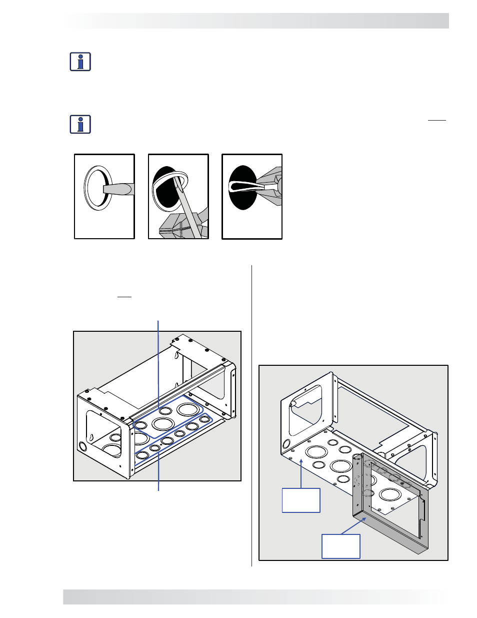
Remove one of these knockouts in order
to run the communication cables from
the router to the inverters.
Do not remove any these front knock-
outs if the router* is attached to the MPX
(see also Figure 3-4).
Figure 3-3, Removing MPX Knockouts
Figure 3-4, MPX with RTR Bracket
Bottom
of MPX
RTR
bracket
* The router and bracket are only used
if inverters are to be parallel stacked.
Conduit Knockouts
Info: Knockouts can be easily removed by tapping the edge with a straight bladed screw-
driver and a hammer, then
twist out with pliers; refer to Figure 3-2. Ensure that no debris
remains inside the MPX after removing the knockouts.
The MPX
comes standard with knockouts for 1/2”, 3/4”, 1”, 1 1/2”, and 2” conduits. Refer to Figure
3-
1 for the location of these conduit knockouts.
Select the appropriate knockout that is closest to
the terminal to which you are running the cable/wire (see Figures 3-1 and 3-3).
Info: Identify and remove whatever MPX knockouts you will need for your installation prior
to attaching the MPX to the MP enclosure. It is much easier to do this now rather than once
the MPX is attached.
Figure 3-2, Removing
a Knockout
Note: The RTR bracket below is shown
mounted on the right side of the MPX. The
bracket can also be mounted on the left side
of the MPX.
Do not attach the RTR bracket to the MPX/
MP enclosure at this time (the bracket will be
attached later in Section 3.1.8).