Yaskawa SmartTrac AC1 User Manual
Page 65
SMART TRAC AC1
Technical Manual TM 3554-000 Smart Trac AC1 Maintenance
••
7-3
5. Disconnect the 9-pin RS-232 cable at connector J5 on the Smart Trac
CPU card.
Model numbers beginning
with STACS-A080 and
above,STACS-B041 and
above, STACS-C027 and
above or STACW- models
with the same succeeding four
digits do not require removal
of the adapter ring.
6. Using the phillips head screwdriver, remove two screws which secure
the adapter ring to the main chassis. Press inward on the main chassis
housing at the location of two tabs on the right side of the adapter ring
and lift to free the tabs. Remove the door with the adapter ring.
TIP: Hold the lower standoff
(next in stack) with pliers
while turning standoff to be
removed with hex head
driver.
7. Using the 4.5mm hex head driver and pliers, remove four standoffs
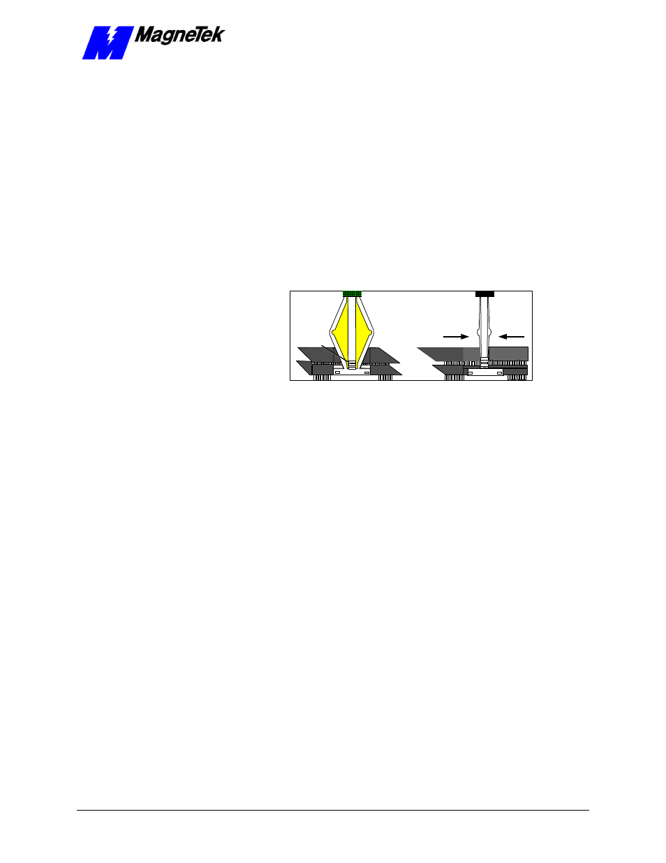
from the topmost card.
Squeeze to lift
cards apart
Position
rectangular
"jacks"
around
edges of
PCBs
Figure 12.
Using thePC/104 card extraction tool
8. Using the PC/104 card extraction tool, remove the topmost card from
the others. Lift the card slightly on one side, then move to another side
and lift the card slightly again. In this manner, work your way around
the card to remove it without damaging connecting pins.