Yaskawa SmartTrac AC1 User Manual
Page 39
SMART TRAC AC1
Technical Manual TM 3554-000 Smart Trac AC1 Installation
••
4-19
19. Disconnect the ribbon cable or wiring harness attached to the Digital
Operator from connector PCB 1CN.
20. Connect the Digital Operator to its normal location on connector J4 on
the Smart Trac CPU card.
21. Power up the drive.
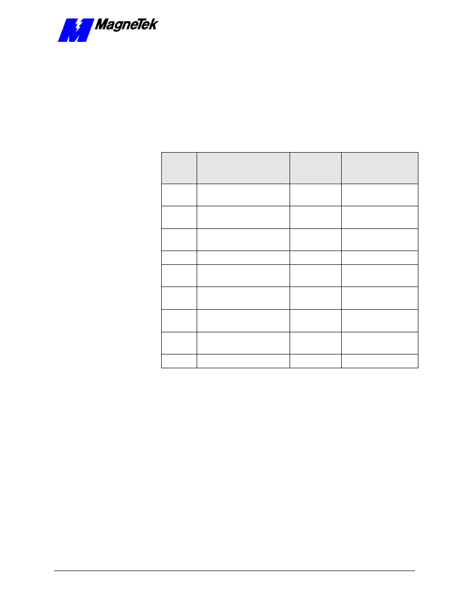
22. Load parameters as follows:
Table 7.
Motor Setup Parameters
Para-
meter
Description
Numeric
Parameter
Number
Displayed
Description
E2-01
Motor rated current
48
RATED MOTOR
AMPS
E2-02
Motor rated slip
47
MOTOR RATED
SLIP
E2-03
Motor no-load current
49
MTR NO LOAD
AMPS
E2-04
Number of motor poles
50
MOTOR POLES
E2-05
Motor line-to-line
resistance
51
MTR TERM RES.
E2-06
Motor leakage inductance
52
MTR LEAKAGE
IND.
E2-07
Motor iron core saturation
coefficient 1
53
MTR SAT COEF 1
E2-08
Motor iron core saturation
coefficient 2
54
MTR SAT COEF 2
E2-09
Motor mechanical loss
55
MTR MECH LOSS
- Tag Generator (30 pages)
- MP3300iec (82 pages)
- 1000 Hz High Frequency (18 pages)
- 1000 Series (7 pages)
- PS-A10LB (39 pages)
- iQpump Micro User Manual (300 pages)
- 1000 Series Drive Option - Digital Input (30 pages)
- 1000 Series Drive Option - CANopen (39 pages)
- 1000 Series Drive Option - Analog Monitor (27 pages)
- 1000 Series Drive Option - CANopen Technical Manual (37 pages)
- 1000 Series Drive Option - CC-Link (38 pages)
- 1000 Series Drive Option - CC-Link Technical Manual (36 pages)
- 1000 Series Drive Option - DeviceNet (37 pages)
- 1000 Series Drive Option - DeviceNet Technical Manual (81 pages)
- 1000 Series Drive Option - MECHATROLINK-II (32 pages)
- 1000 Series Drive Option - Digital Output (31 pages)
- 1000 Series Drive Option - MECHATROLINK-II Technical Manual (41 pages)
- 1000 Series Drive Option - Profibus-DP (35 pages)
- AC Drive 1000-Series Option PG-RT3 Motor (36 pages)
- Z1000U HVAC MATRIX Drive Quick Start (378 pages)
- 1000 Series Operator Mounting Kit NEMA Type 4X (20 pages)
- 1000 Series Drive Option - Profibus-DP Technical Manual (44 pages)
- CopyUnitManager (38 pages)
- 1000 Series Option - JVOP-182 Remote LED (58 pages)
- 1000 Series Option - PG-X3 Line Driver (31 pages)
- SI-EN3 Technical Manual (68 pages)
- JVOP-181 (22 pages)
- JVOP-181 USB Copy Unit (2 pages)
- SI-EN3 (54 pages)
- SI-ET3 (49 pages)
- MECHATROLINK-III (35 pages)
- EtherNet/IP (50 pages)
- SI-EM3 (51 pages)
- 1000-Series Option PG-E3 Motor Encoder Feedback (33 pages)
- 1000-Series Option SI-EP3 PROFINET (56 pages)
- PROFINET (62 pages)
- AC Drive 1000-Series Option PG-RT3 Motor (45 pages)
- SI-EP3 PROFINET Technical Manual (53 pages)
- A1000 Drive Option - BACnet MS/TP (48 pages)
- 120 Series I/O Modules (308 pages)
- A1000 12-Pulse (92 pages)
- A1000 Drive Software Technical Manual (16 pages)
- A1000 Quick Start (2 pages)
- JUNMA Series AC SERVOMOTOR (1 page)
- A1000 Option DI-101 120 Vac Digital Input Option (24 pages)