Smart trac grounding – Yaskawa SmartTrac AC1 User Manual
Page 29
SMART TRAC AC1
Technical Manual TM 3554-000 Smart Trac AC1 Installation
••
4-9
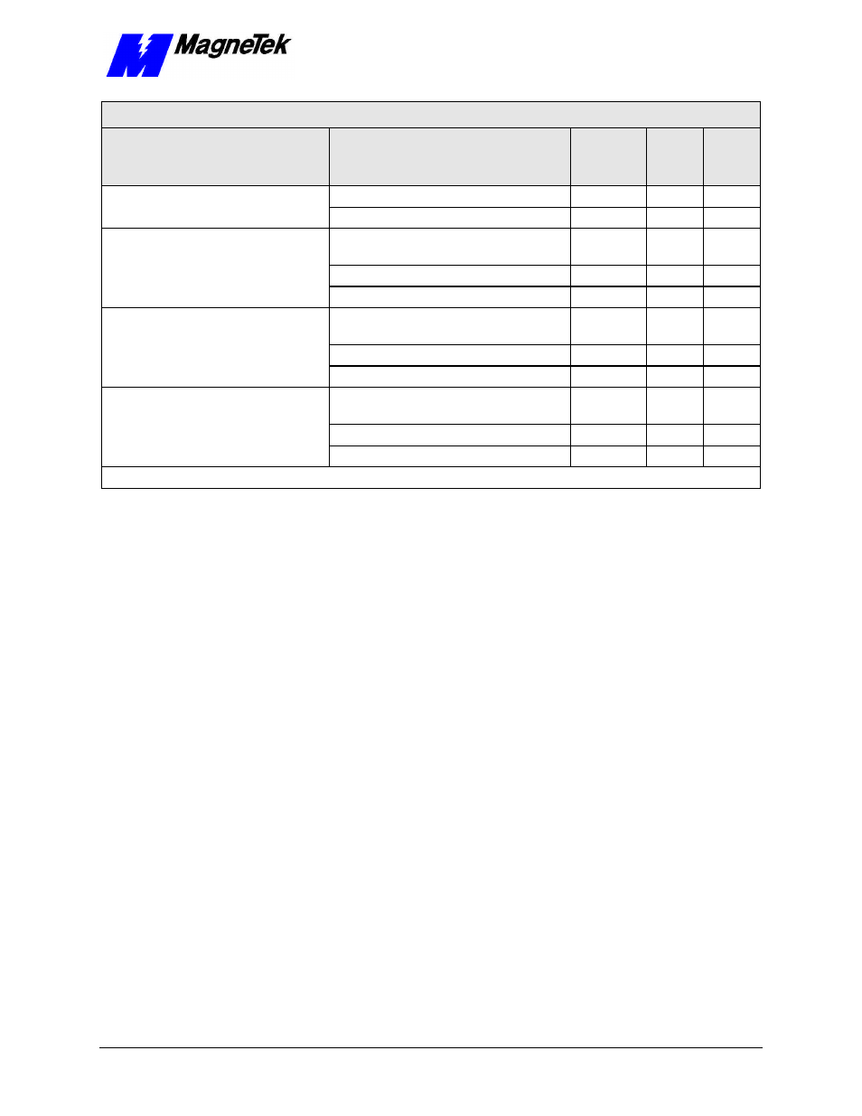
Wire Sizing for Main Circuit, 600 Volt
Smart Trac AC1 Model No.
Terminal Symbol
Terminal
Screw
Wire
Size
(AWG)
Wire
Size
(mm
2
)
GND
*
4-2
22-30
1(r), 2(s)
M4
14-10
2-5.5
L1(R), L2(S), L3(T),
, 1
, T1(U), T2(V),
T3(W)
M10
3/0=300 80-150
GND
*
4-2/0
22-60
STAC*C130
1(r), 2(s)
M4
14-10
2-5.5
L1(R), L2(S), L3(T),
, 1
, T1(U), T2(V),
T3(W)
M12
300-400 150-200
GND
*
4-2/0
22-60
STAC*C172
1(r), 2(s)
M4
14-10
2-5.5
L1(R), L2(S), L3(T),
, 1
, T1(U), T2(V),
T3(W)
M12
350-400 180-200
GND
*
3-2/0
30-60
STAC*C200
1(r), 2 (s)
M4
14-10
2-5.5
* Indicates terminal uses a pressure lug.
Your Smart Trac AC1 must be solidly grounded using main circuit ground
terminal GND. Refer to the latest edition of the National Electrical Code (NEC),
Article 250, Grounding, for proper grounding methods, especially ground rod
requirements. Select lead size suitable for size of terminal screw. Make the
length as short as possible.
Never ground the Smart Trac AC1 with the same common as welding machines,
motors, or other large-current electrical equipment. Where several Smart Trac
AC1s are used, ground each directly or daisy chain each to the machine ground
bar or ground rod.
Refer to Figure 2
. Do not form a loop with the ground
leads.
Smart Trac
Grounding