Warning warning – Yaskawa SmartTrac AC1 User Manual
Page 30
SMART TRAC AC1
4-10
••
Smart Trac AC1 Installation Technical Manual TM 3554-000
Star
washer
between
cabinet
and bus
wire
Electrical
Cabinet
Copper
Bus
Electrical
Cabinet
Copper
Bus
GROUND
POLE
NOT
ACCEPTABLE
GROUND
POLE
NOT
ACCEPTABLE
NOT
ACCEPTABLE
GROUND
POLES
ACCEPTABLE
Electrical
Cabinet
ACCEPTABLE
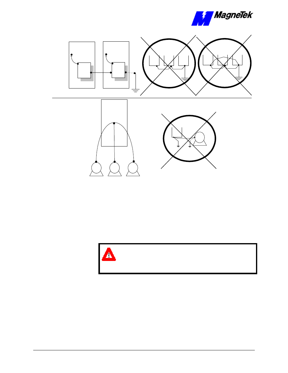
Figure 2. Grounding of Three Smart Trac AC1s (top) and Grounding of Smart
Trac AC1 with Vector Controlled Motor (VCM) (bottom)
Proper wiring practices and relative locations within the electrical path, from
line to load, are shown in
." Your application may use some or all of the devices
shown. Disregard items depicted which do not match those in your Smart Trac
AC1 configuration.
WARNING
WARNING
Disconnect all power to Smart Trac AC1. Do not remove the front
cover while input power is ON. Failure to comply may result in
personal injury or death.
Mount all power option devices as close to the Smart Trac AC1 as possible.
Keep electrical connections as short as possible. For Models with base
designations of STAC-A003 through STAC-A064, STACWA003 through
STACWA064, STAC-B001 through STAC-B034, and STACWB001 through
STACWB034, an input or DC reactor should be used.
Basic control circuit (signal) terminations on the Smart Trac AC1 are shown in
the "Simplified Customer Connection Diagram."The use of these terminals,
however, is dependent on the needs of the the application program. Terminal
numbers and their function are listed in the table "Terminal Definitions of the
Inverter Control Card."
Connecting Auxiliary
Input and Output
Power Option
Devices
Connecting the
Control Circuit