Yaskawa SmartTrac AC1 User Manual
Page 24
SMART TRAC AC1
4-4
••
Smart Trac AC1 Installation Technical Manual TM 3554-000
•
Never allow wire leads to contact metal surfaces. Short-circuit may
result.
•
Never connect power factor correction capacitors or noise filters to
Smart Trac AC1 output.
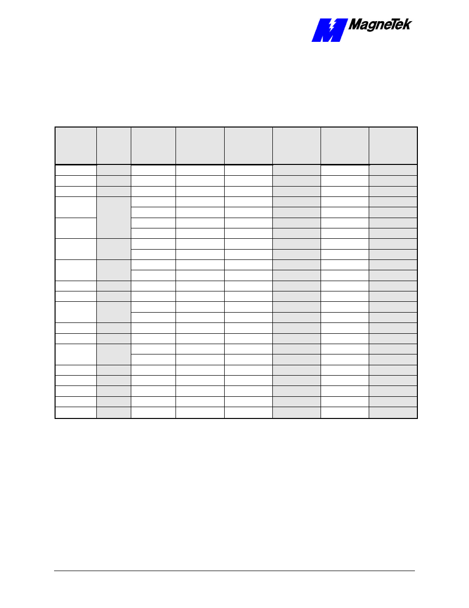
Table 2. Terminal screws, connectors and clamping torque by wire size
Wire
Size
(AWG)
Wire
Size
(mm
2
)
Terminal
Screw
Closed-
Loop
Connector
Clamping
Torque
Steel,
lb-in
Clamping
Torque
Steel, N-m
Clamping
Torque
Copper,
lb-in
Clamping
Torque
Copper,
lb-in
20
0.50
M3.5
1.25-3.5
7.8
0.9
7.0
0.8
18
0.75
M4
1.25-4
13.0
1.5
10.4
1.2
16
1.25
M4
1.25-4
13.0
1.5
10.4
1.2
M4
2-4
13.0
1.5
10.4
1.2
14
2
M5
2-5
26.1
20.9
3.1
2.4
M4
3.5-4
13.0
1.5
10.4
1.2
12
3.5
M5
3.5-5
26.1
20.9
3.1
2.4
M4
5.5-4
13.0
1.5
10.4
1.2
10
5.5
M5
5.5-5
26.1
20.9
3.1
2.4
M5
8-5
26.1
20.9
3.1
2.4
8
8
M6
8-6
40.9
34.8
4.8
4.1
6
14
M6
14-6
40.9
34.8
4.8
4.1
4
22
M8
22-8
100.0
82.6
11.7
10.7
M8
38-8
100.0
82.6
11.7
10.7
2
38
M10
38-10
182.6
156.5
21.4
18.4
1/0
60
M10
60-10
182.6
156.5
21.4
18.4
3/0
80
M10
80-10
182.6
156.5
21.4
18.4
M10
100-10
182.6
156.5
21.4
18.4
4/0
100
M12
100-12
313.0
191.3
36.7
23.1
MCM300
150
M12
150-12
313.0
191.3
36.7
23.1
MCM400
200
M12
200-12
313.0
191.3
36.7
23.1
MCM650
325
M12
325-12
313.0
191.3
36.7
23.1
M16
325-16
313.0
191.3
36.7
23.1