Yaskawa YASNAC PC NC Maintenance Manual User Manual
Page 155
PC NC Maintenance Manual
The VS-626M5
4-134
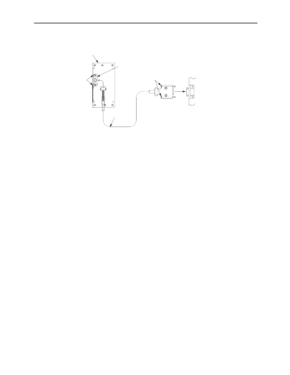
Figure 4.21: Extension Cable Installation
Digital Operator Functions
The digital operator enables the following:
(1)
Control Signal Status Display
The status of the control signals for each unit is displayed by
monitoring the operation status. For the display items, see
APPENDIX 5.
(2)
Control Constants Display and Setup
Control constants must be set up for normal operation in compli-
ance with the specifications. APPENDIX 6 lists the control con-
stants.
(3)
Protective Functions Display
If an error occurs during operation, protective functions are dis-
played. (Refer to Tables 18 to 20.) These are not displayed when
operation is normal.
(4)
Digital Operator Function
Stand-alone operation without sequence input signals or speed
reference is possible. This function is effective for the test run of
the inverter/converter connected only to a motor.
Digital operator
(Back of JVOP-132)
Cable holder
(Make sure it's not reversed.)
Attach the cable
holder with tapping
screws M3 ~10.
Connector code for
digital operator con
nection
3CN
Connector screws
Control PC board
Extension cable
Digital operator JVOP-132
(rear view)
Cable holder
(Ensure it is not reversed.)
Connector screws
Control PC board
Extension cable
Connector code for
digital operator
connection
3CN
Attach the cable
holder with tapping
screws.
Extension cable