Specification g5 specification g7 specification – Yaskawa GPD 515/G5 to G7 User Manual
Page 7
Product Transition Guide
GPD515/G5 to G7
__________________________
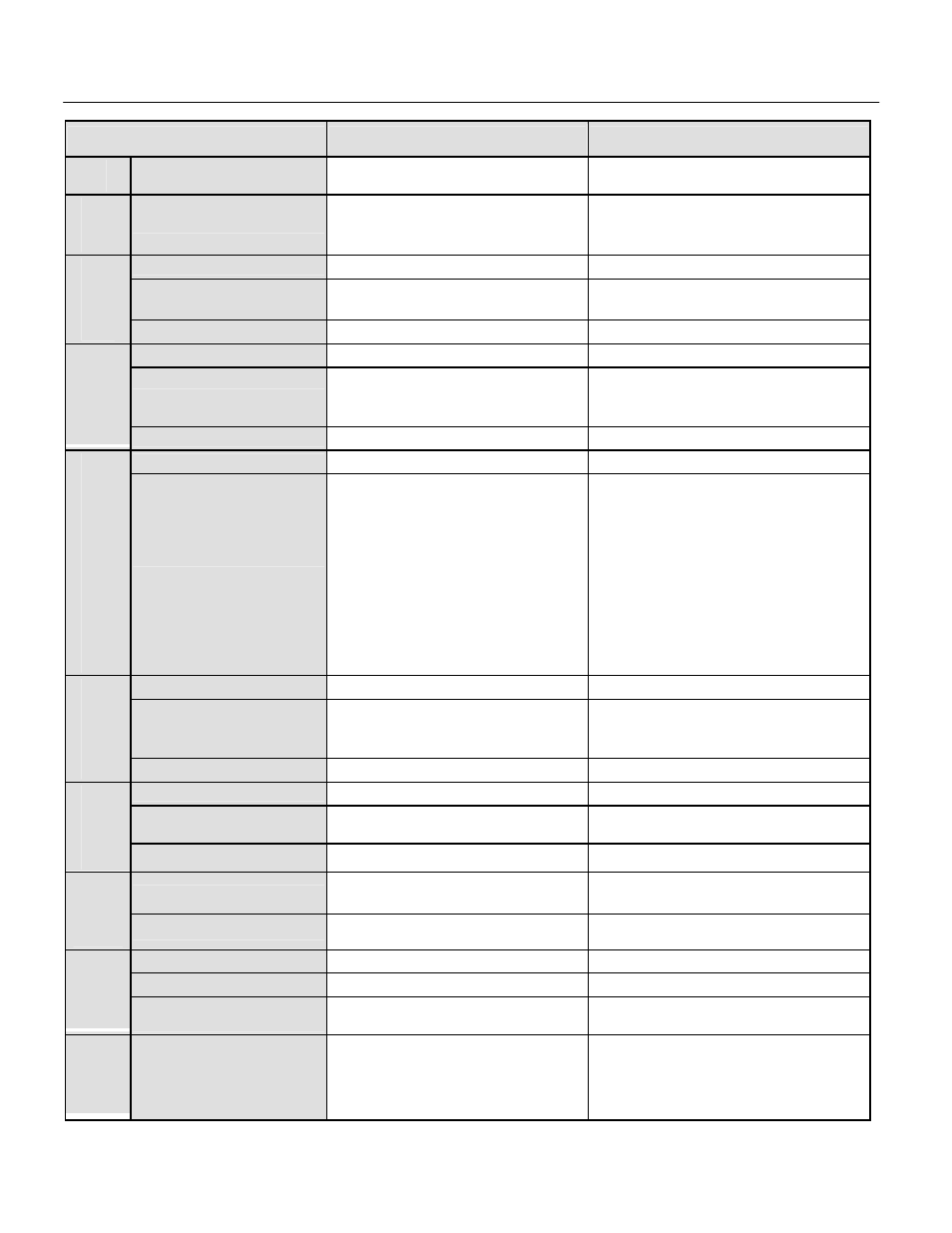
Specification
G5 Specification
G7 Specification
I/O
Quick disconnect I/O
terminals
No Yes
Ana
log
Inputs
Programmable functions
39 45
Quantity
0-±10VDC x 2
0-±10VDC/4-20mA x 2
Type
-10-10VDC x 2
(8 bit plus sign)
-10-10VDC or 4-20mA x 2
(8 bit plus sign)
Ana
log
Outputs
Programmable functions
27 30
Quantity
8 12
Type
24VDC, NPN
Photo coupler isolation, 8mA
24VDC, sinking or sourcing (NPN/PNP)
Photo coupler isolation, 8mA
Internal or external power supply
Digital
Inputs
Programmable functions
45 51
Quantity
4 6
D
ig
it
a
l
Outputs
Type
• Qty 1: Programmable: Form A,
250VAC, 1A, 30VDC, 1A
• Qty 1: Dedicated Fault, Form C,
250VAC, 1A, 30VDC, 1A
• Qty 2: Programmable, photo-
coupler (open collector output),
48V, 50mA, common emitter
connection
• Qty 3: Programmable: Form A,
250VAC, 1A, 30VDC, 1A
• Qty 1: Dedicated Fault, Form C,
250VAC, 1A, 30VDC, 1A
• Qty 2: Programmable, photo-coupler
(open collector output), 48V, 50mA,
separate emitter connection
Quantity
0 1
Signal level
~
0-32kHz, low level: 0.0-0.8VDC high
level: 3.5-13.2VDC, duty cycle: 30-70%,
3kohm
P
u
ls
e
Input
Programmable functions
~ 4
Quantity
0 standard (1 with option)
1
Signal level
~
0-32kHz, 9.0VDC, 2.2kohm
Pu
lse
Output
Programmable functions
~ 6
Braking DB transistor
Built-in to G5M27P5 (10HP)
Built-in to G5M4015 (25HP)
Built-in to G7U2015 (20HP)
Built-in to G7U4015 (25HP)
S
to
p
p
in
g
Flux/High slip braking
No Yes
Modular replacement
No Yes
On/Off control
No Yes
C
o
o
li
n
g
Fa
n
Cumulative fan operation
time
No Yes
Desig
n
F
eatu
res
Auto-tuning
Rotational
Rotational
Stationary
Stationary (primary resistance only)
PL.G7.02.TransitionGuide 4/21/04
Page 7 of 38
Yaskawa Electric America, Inc