Parameters a - 27 – Yaskawa E7 Drive User Manual User Manual
Page 195
Parameters A - 27
Monitor
U1-13
Cumulative Operation Time
Elapsed Time
Displays total operating or power-on time of the Drive.
U1-14
Software Number
FLASH ID
Displays Drive's software number.
U1-15
Terminal A1 Input Voltage
Term A1 Level
Displays the input voltage on Terminal A1, as a percentage of
10V DC.
U1-16
Terminal A2 Input Voltage
Term A2 level
Displays the input current (or voltage) on Terminal A2, as a
percentage of 20mA (or 10 V DC).
U1-18
Motor Secondary Current (I
q
)
Mot SEC Current
Displays the amount of current being used by the motor to
produce torque (Iq).
U1-20
Output Frequency After Soft Start
SFS Output
Displays the frequency reference (speed command) after the
accel and decel ramps. (units changeable via o1-03)
U1-24
PI Feedback Value
PI Feedback
Displays the feedback signal when PI control is used.*
U1-28
CPU Number
CPU ID
Displays control board hardware revision.
U1-29
kWh
kWh Lo 4 Digits
Displays the accumulated kWh.
U1-30
MWh
kWh Hi 5 Digits
Displays the accumulated MWh.
U1-34
First Parameter Causing an OPE
OPE Detected
Displays the parameter number causing an "OPE" fault.
U1-36
PI Input
PI Input
Displays the "error" in the PI regulator. (U1-36 = PI Setpoint -
PI Feedback).
U1-37
PI Output
PI Output
Displays the output of the PI as a percentage of maximum
frequency (E1-04).
U1-38
PI Setpoint
PI Setpoint
Displays the setpoint of the PI regulator (U1-38 = PI reference
+ PI bias).*
U1-39
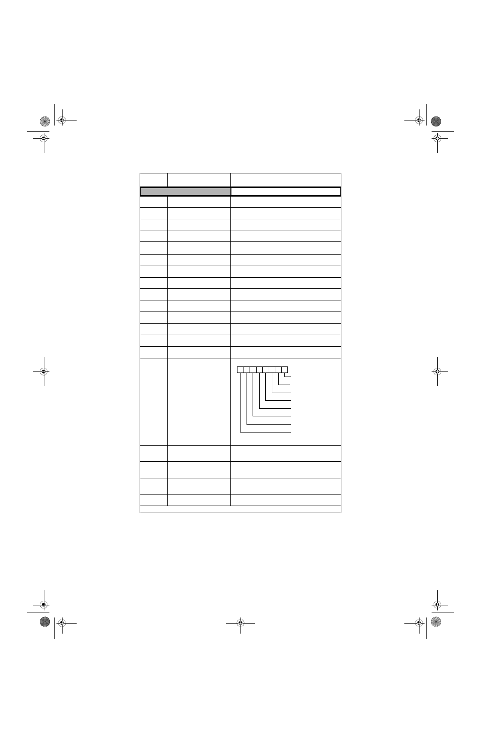
Memobus Communication Error
Code
Transmit Err
U1-40
Heatsink Cooling Fan Operation
Time
FAN Elapsed Time
Displays total operating time of the heatsink cooling fan.
U1-51
Auto Mode Frequency Reference
Value
AUTO Mode Fref
Displays the frequency reference (speed command) when in
auto mode.
U1-52
Hand Mode Frequency Reference
Value
HAND Mode Fref
Displays the frequency reference (speed command) when in
hand mode, or displays Terminal A2 when differential mode is
selected.
U1-53
PI Feedback 2 Value
PI Feedback 2
Displays PI feedback 2 value.
** Units depend on b5-31 setting; scaling is set by b5-20
Table A.2 Monitor List (Continued)
Parameter
No.
Parameter Name
Digital Operator Display
Description
1: CRC error
1: Data length error
Not used. Always 0.
1: Parity error
1: Overrun error
1: Fleming error
1: Timeover
Not used. Always 0
.
0 0 0 0 0 0 0 0
TM_E7_01_07182008.book Page 27 Wednesday, July 23, 2008 2:35 PM