Physical installation 1 - 6 – Yaskawa E7 Drive User Manual User Manual
Page 16
Physical Installation 1 - 6
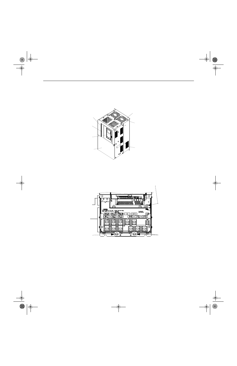
Models CIMR-E7U2022 thru 2110 (30HP and above @ 208V/240V) and 4030 thru
4300 (40HP and above @ 480V)
The external appearance, component names, and terminal arrangement of the Drive are shown in Fig 1.6 and 1.7.
Fig 1.6 Drive Appearance
Fig 1.7 Terminal Arrangement (Terminal Cover Removed)
Mounting holes
Cooling fan
Nameplate
Drive cover
Front cover
Digital Operator
Terminal cover
Mounting holes
Cooling fan
Nameplate
Drive cover
Front cover
Digital Operator
Terminal cover
Charge indicator
Control circuit
terminals
Main circuit
terminals
Ground terminal
Ground terminal
TM_E7_01_07182008.book Page 6 Wednesday, July 23, 2008 2:35 PM
This manual is related to the following products: