E2 motor setup -32, E2 motor setup – Yaskawa E7 Drive User Manual User Manual
Page 106
Programming 5 - 32
E1-12 Mid Output Voltage B
E1-13 Base Voltage
Setting Range:
0.0 to 255.0V (240V Models)
0.0 to 510.0V (480V Models)
Factory Defaults: 0.0V (240V Models)
0.0V (480V Models)
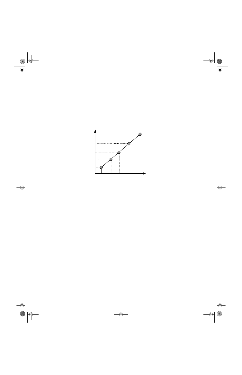
To set up a custom V/f pattern, program the points shown in the diagram below using parameters E1-04 through E1-13. Be
sure that the following condition is true:
E1-09
≤
E1-07
≤
E1-06
≤
E1-11
≤
E1-04
Fig 5.22 Custom V/f Pattern Programming Curve
Increasing the voltage in the V/f pattern increases the available motor torque. However, when setting a custom V/f pattern,
increase the voltage gradually while monitoring the motor current, to prevent:
•
Drive faults as a result of motor over-excitation
•
Motor overheating or excessive vibration
E2 Motor Setup
E2-01 Motor Rated Current
Setting Range:
Model Dependent (see Appendix B)
Factory Default: Model Dependent
The Motor Rated Current parameter (E2-01) is necessary information for the Drive motor protection function. The motor over-
load protection parameter L1-01 is enabled by default. In addition, motor rated current is used by the torque compensation
function to insure optimum torque production. Set E2-01 to the full load amps (FLA) value stamped on the motor’s
nameplate. During Auto-tuning, it is required for the operator to enter the motor rated current in parameter T1-04 on the
Auto-Tuning menu. If the Auto-tuning operation completes successfully, the value entered into T1-04 will be also written into
E2-01.
Frequency
E1-09 E1-07
E1-06
E1-04
E1-11
Max Voltage E1-05
Mid Voltage B E1-12
Mid Voltage A E1-08
Base Voltage E1-13
Min Voltage E1-10
Min
Freq
Max
Freq
Base
Freq
Mid
Freq
A
Mid
Freq B
Freq A
TM_E7_01_07182008.book Page 32 Wednesday, July 23, 2008 2:35 PM