Diagnostic & troubleshooting 6 - 11 – Yaskawa E7 Drive User Manual User Manual
Page 147
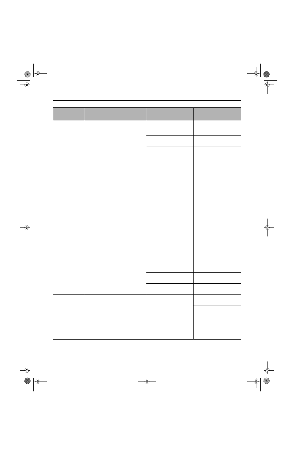
Diagnostic & Troubleshooting 6 - 11
OV
DC Bus Overvolt
(Flashing)
DC Bus Overvoltage
208-240Vac: Trip point is
≥ 400Vdc
480Vac: Trip point is
≥ 800Vdc
High input voltage at R/L1,
S/L2 and T/L3
Check the input circuit and
reduce the input power to within
specifications
Extend the time in C1-02
The deceleration time is set too
short
Power factor correction
capacitors are being used on the
input to the Drive
Remove the power factor correc-
tion capacitors
OVRD
Emergcy
Override
Emergency Override
Emergency Override is active
Forward or Reverse Emergency
Override input is closed
When the Forward (H1-0X = 81)
or Reverse (H1-0X = 82) Emer-
gency Override multi-function
input is closed, the drive will run
at either the B1-14 reference (B1-
15 = 0) or the AUTO reference
(B1-15 = 1) and “OVRD Emer-
gency Override” will be dis-
played on the digital operator.
If the Drive Enable
(H1-0X =
6A) or Bypass Drive Enable (H1-
0X = 70) is programmed, the
emergency override function can
only be activated when the
Enable input is open. If the
Enable input is closed at any time
during emergency override, the
drive will stop.
PRHT
Motor Preheating
Motor Preheating
Motor is preheating
Motor Preheat 2 input is closed
- - -
UV
DC Bus Undervolt
(Flashing)
DC Bus Undervoltage
The DC bus voltage is
≤ L2-05
208-240Vac: Trip point is
≤ 190Vdc
480Vac: Trip point is
≤ 380Vdc
Low input voltage at R/L1, S/L2
and T/L3
Check the input circuit and
increase the input power to
within specifications
The acceleration time is set too
short
Extend the time in C1-01
Voltage fluctuation of the input
power is too large
Check the input voltage
UV2
CTL PS Undervolt
Control Power Supply Undervoltage of the
control circuit when running
External load connected pulling
down the Drive power supplies
Cycle power off and on to the
Drive
Repair or replace the Power PCB/
Gate Drive PCB
UV3
MC Answerback
Soft Charge Circuit Fault
The pre-charge contactor opened while the
Drive was running
Contacts on the soft charge
contactor are dirty and the soft
charge contactor does not
function mechanically
Cycle power off and on to the
Drive
Check the condition of the soft
charge contactor
Table 6.2 Alarm Displays and Processing
Digital
Operator Display
Description
Cause
Corrective Action
TM_E7_01_07182008.book Page 11 Wednesday, July 23, 2008 2:35 PM