Diagnostic & troubleshooting 6 - 6 – Yaskawa E7 Drive User Manual User Manual
Page 142
Diagnostic & Troubleshooting 6 - 6
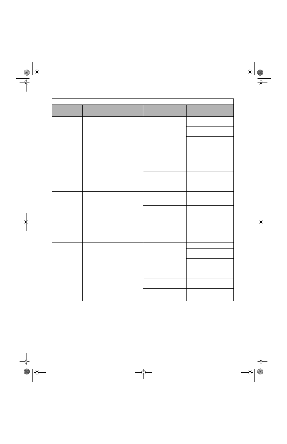
OH4
Motor Overheat 2
Motor Overheating Fault
The Drive stops operation according to the
setting of L1-04.
Overheating of motor as
measured by motor thermistor
Recheck the cycle time and the
size of the load
Recheck the accel/decel time
(C1-01 and C1-02)
Recheck the V/F pattern (E1-01
thru E1-13)
Recheck the motor rated current
value (E2-01)
OL1
Motor Overloaded
Motor Overload
Designed to protect the motor.
Fully adjustable from parameter E2-01
The load is too large. The
cycle time is too short at the
accel/decel time
Recheck the cycle time and the
size of the load as well as the
times set in C1-01 and C1-02
The voltage of the V/F pattern
is high
Review the V/F pattern
parameters, E1-01 thru E1-13
Motor rated current setting is
improper
Check the motor rated current
value in E2-01
OL2
Inv Overloaded
Drive Overload
Designed to protect the Drive
The load is too large. The
cycle time is too short at the
accel/decel time
Recheck the cycle time and the
size of the load as well as the
times set in C1-01 and C1-02
The voltage of the V/F pattern
is high
Review the V/F pattern
parameters, E1-01 thru E1-13
The size of the Drive is small
Change to a larger size Drive
OL3
Overtorque Det 1
Overtorque Detection 1
Drive output current > L6-02 for more than
the time set in L6-03
Motor is overloaded
Ensure the values in L6-02 and
L6-03 are appropriate
Check application/machine
status to eliminate fault
OPR
Oper Disconnect
Digital Operator Connection Fault
The Drive will stop if the digital operator is
removed when the Drive is commanded to
run through the digital operator
The digital operator is not
attached or the digital opera-
tor connector is broken
Attach the digital operator
Check the digital operator
connector
Verify the setting of o2-06
OV
DC Bus Overvolt
DC Bus Overvoltage
208-240Vac: Trip point is
≥ 400Vdc
480Vac: Trip point is
≥ 800Vdc
High input voltage at R/L1,
S/L2 and T/L3
Check the input circuit and
reduce the input power to within
specifications
The deceleration time is set
too short
Extend the time in C1-02
Power factor correction
capacitors are being used on
the input to the Drive
Remove the power factor
correction capacitors
Table 6.1 Fault Displays and Processing
Digital
Operator Display
Description
Cause
Corrective Action
TM_E7_01_07182008.book Page 6 Wednesday, July 23, 2008 2:35 PM