For det, A1000, 5 installation procedure – Yaskawa SI-ET3 User Manual
Page 15: Connection diagram
5 Installation Procedure
YASKAWA ELECTRIC SIEP C730600 62B 1000-Series Option SI-ET3 Technical Manual
15
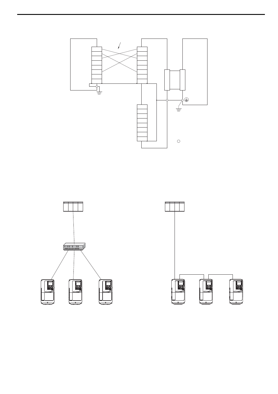
Connection Diagram
Figure 8 Option Connection Diagram
Communication Cable Wiring
The dual communication cable ports on the option board act as a switch to allow for flexibility in cabling topology.
For example, a traditional star network topology may be employed by using a single port on the option board.
Alternatively, a daisychained approach may be employed by using both communication cable ports. This second
approach reduces the requirements of MECHATROLINK-III hub module ports.
Figure 8
Figure 9 Topology Options
<1> Use connector CN1 or CN2 to connect with the MECHATROLINK-III master. Refer to
A1000
TXD_P
TXD_N
RXD_P
NC
NC
RXD_N
NC
NC
TXD_P
TXD_N
RXD_P
NC
NC
RXD_N
NC
NC
MECHATROLINK-III
Master
SI-ET3
CN2
<1>
TXD_P
TXD_N
RXD_P
NC
NC
RXD_N
NC
NC
CN1
<1>
FE
Drive
control circuit terminal
MECHATROLINK-III
Communication Cable
PLC
MECHATROLINK-III
Hub Module
A1000
A1000
A1000
A1000
A1000
A1000
PLC
A1000
- Tag Generator (30 pages)
- MP3300iec (82 pages)
- 1000 Hz High Frequency (18 pages)
- 1000 Series (7 pages)
- PS-A10LB (39 pages)
- iQpump Micro User Manual (300 pages)
- 1000 Series Drive Option - Digital Input (30 pages)
- 1000 Series Drive Option - CANopen (39 pages)
- 1000 Series Drive Option - Analog Monitor (27 pages)
- 1000 Series Drive Option - CANopen Technical Manual (37 pages)
- 1000 Series Drive Option - CC-Link (38 pages)
- 1000 Series Drive Option - CC-Link Technical Manual (36 pages)
- 1000 Series Drive Option - DeviceNet (37 pages)
- 1000 Series Drive Option - DeviceNet Technical Manual (81 pages)
- 1000 Series Drive Option - MECHATROLINK-II (32 pages)
- 1000 Series Drive Option - Digital Output (31 pages)
- 1000 Series Drive Option - MECHATROLINK-II Technical Manual (41 pages)
- 1000 Series Drive Option - Profibus-DP (35 pages)
- AC Drive 1000-Series Option PG-RT3 Motor (36 pages)
- Z1000U HVAC MATRIX Drive Quick Start (378 pages)
- 1000 Series Operator Mounting Kit NEMA Type 4X (20 pages)
- 1000 Series Drive Option - Profibus-DP Technical Manual (44 pages)
- CopyUnitManager (38 pages)
- 1000 Series Option - JVOP-182 Remote LED (58 pages)
- 1000 Series Option - PG-X3 Line Driver (31 pages)
- SI-EN3 Technical Manual (68 pages)
- JVOP-181 USB Copy Unit (2 pages)
- JVOP-181 (22 pages)
- SI-EN3 (54 pages)
- MECHATROLINK-III (35 pages)
- EtherNet/IP (50 pages)
- SI-EM3 (51 pages)
- 1000-Series Option PG-E3 Motor Encoder Feedback (33 pages)
- 1000-Series Option SI-EP3 PROFINET (56 pages)
- PROFINET (62 pages)
- AC Drive 1000-Series Option PG-RT3 Motor (45 pages)
- SI-EP3 PROFINET Technical Manual (53 pages)
- A1000 Drive Option - BACnet MS/TP (48 pages)
- 120 Series I/O Modules (308 pages)
- A1000 12-Pulse (92 pages)
- A1000 Drive Software Technical Manual (16 pages)
- A1000 Quick Start (2 pages)
- JUNMA Series AC SERVOMOTOR (1 page)
- A1000 Option DI-101 120 Vac Digital Input Option (24 pages)