SMA Communit-10 User Manual
Page 31
SMA Solar Technology AG
6 Electrical Connection
Installation Manual
Communit-IA-A1-en-22
31
Procedure:
1. Insert the optical fibers into the patch panel from below and splice
using optical fiber pigtails (see the patch panel documentation).
Observe the maximum permissible tension and the minimum
permissible bend radii of the optical fibers.
2. Connect the patch panel to the network switch using the optical fiber patch cables included in the delivery (bend
radius: 100 mm). Observe the send and receive directions of the optical fiber nodes.
6.6 Connecting the Network Cable via the Keystone Jack
The modular patch panel enables the connection of copper cables and optical fiber cables. The module for the copper
cables contains four RJ45 keystone pin connectors that are used to connect the network cables via keystone jacks.
Procedure:
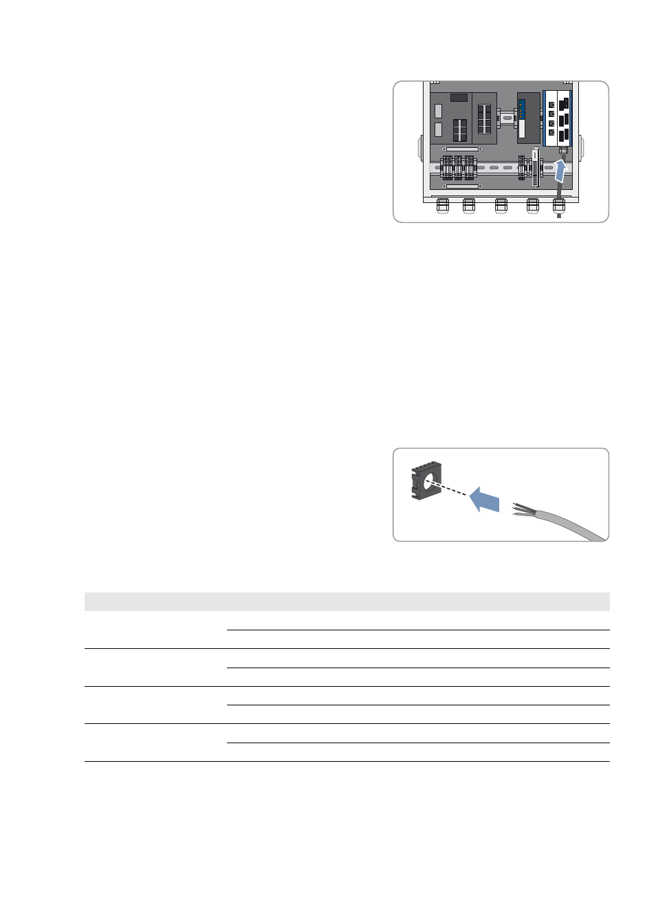
1. Dismantle the network cable by 30 mm.
2. Fold back the braided shielding.
3. Remove the foil shield from the insulated conductor pairs.
4. With the adhesive side facing the inside, attach the aluminum foil from the outside so that it is flush with the braided
shielding.
5. Lead the network cable into the cable organizer.
6. Insert the conductors into the slots of the cable organizer. Observe the appropriate color coding for the standard of
your choice.
7. Shorten protruding conductors.
Insulated conductor pair
Insulated conductor color
Contact -568A
Contact -568B
1
white/blue
5
5
blue
4
4
2
white/orange
3
1
orange
6
2
3
white/green
1
3
green
2
6
4
white/brown
7
7
brown
8
8