SMA Communit-10 User Manual
Page 28
6 Electrical Connection
SMA Solar Technology AG
28
Communit-IA-A1-en-22
Installation Manual
6.3.7 Connecting the Voltage Supply of Your Own Optional Devices
If the Communit is fitted with one or two customer installation locations, you can install your own devices in the Communit
and connect them to the voltage supply.
Cable requirements:
☐ Number of conductors for the AC voltage supply: 3
☐ Number of conductors for the DC voltage supply: 2
☐ Conductor cross-section for rigid cables: 0.14 mm
2
to 1.5 mm
2
☐ Conductor cross-section for flexible cables: 0.14 mm
2
to 1.5 mm
2
(with bootlace ferrule: 0.14 mm
2
to 1.0 mm
2
)
☐ The cable for the AC supply voltage must also include a grounding conductor.
☐ The electric strength of the cable must be suitable for the voltage present on site.
Requirements:
☐ The current and power consumption of the customer devices must not exceed the power reserve of the Communit
(see the Technical Information "Communit").
☐ No supply voltage must be present.
☐ The cable must be correctly inserted in the Communit (see Section 6.2 "Inserting the Cables into the Communication
Connecting the Device at Installation Location 1
1. Strip off the conductor insulation of the cable by 8 mm.
2. If you are using bootlace ferrules, crimp them.
3. If you are using the AC voltage supply, connect the insulated conductors to the plugs of connecting terminal plate
-X320 (see Section 6.3.1 "Connecting Conductors to the Spring-Cage Terminal", page 24). Observe the correct
allocation and ensure that the insulation is not clamped.
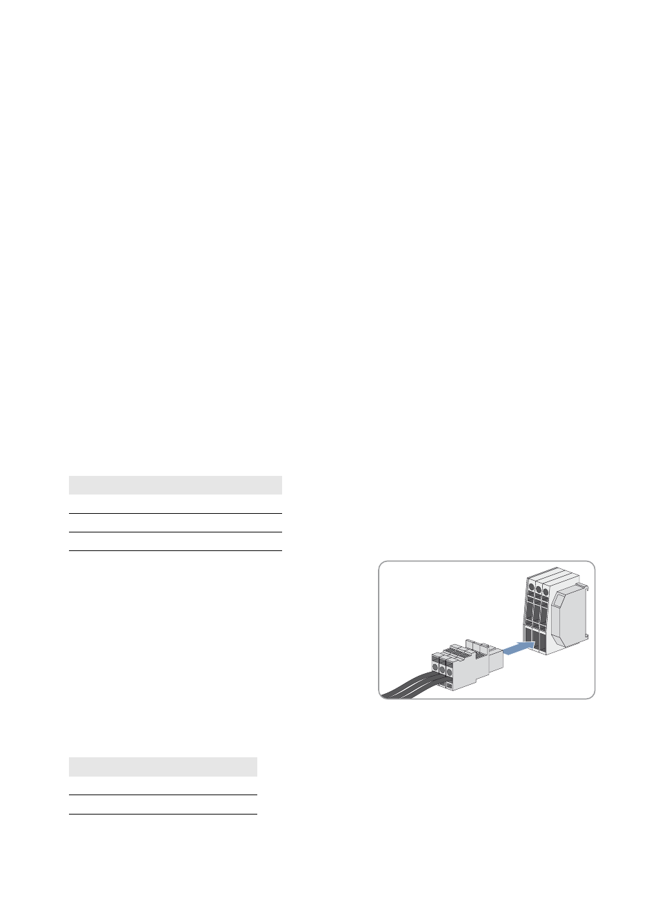
4. Insert the plug into the terminals.
5. If you are using the DC voltage supply, connect the insulated conductors to the plug of the connecting terminal plate
-X461 (see Section 6.3.1 "Connecting Conductors to the Spring-Cage Terminal", page 24). Observe the correct
allocation and ensure that the insulation is not clamped.
Terminal
Signal
1
L
2
N
3
Grounding conductor
Terminal
Signal
1
+24 VDC
2
0 VDC