SMA STP 15000TL Service Manual User Manual
Page 32
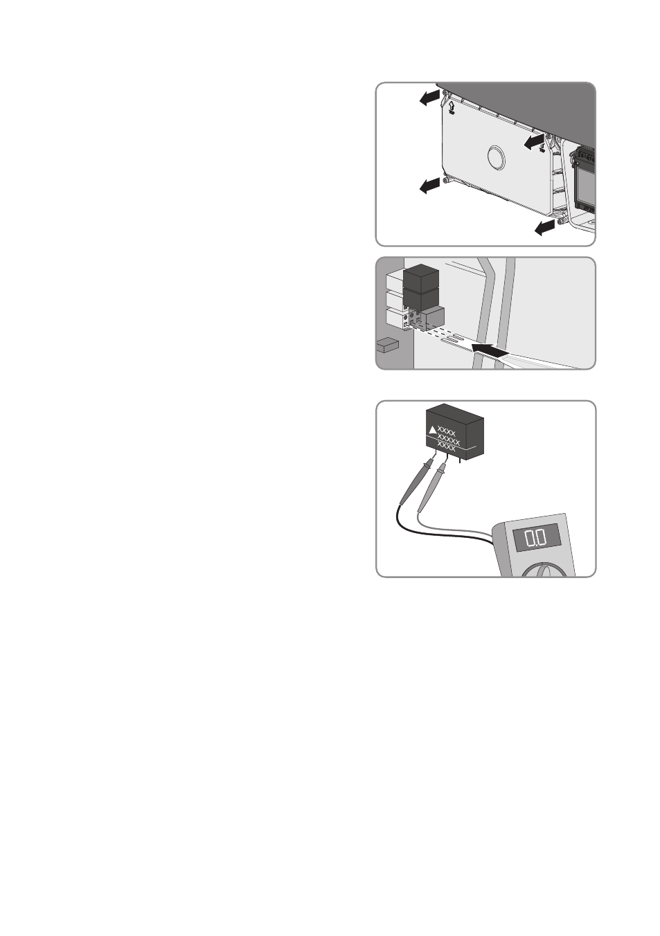
2. Release all four screws of the DC protective
cover using an Allen key (AF 3) and remove the
DC protective cover.
3. Insert the insertion tool into the clamping
contacts of the connecting terminal plate.
4. Remove the varistor from the connecting terminal plate.
5. Use a measuring device to measure whether
there is a conductive connection between the
middle and the left-hand varistor lead. Hold the
varistor with the labeling pointing forward.
If there is no conductive connection, the varistor is defective. SMA Solar Technology AG
recommends replacing all varistors immediately.
• Order new varistors and insertion tools (see Section 14 "Spare Parts", page 42).
• Reinsert old varistors and leave them in place until new varistors and insertion tools are
available.
• If new varistors are available, replace all varistors (see Section 9, page 33).
If a conductive connection is present, contact Service (see Section 15, page 43).
8 Checking the Function of the Varistors
SMA Solar Technology AG
Service Manual
STP15-17TL-10-SG-en-10
32