10 .13 pr ogr amming examples – HEIDENHAIN TNC 620 (340 56x-01) User Manual
Page 450
450
1
0
.13 Pr
ogr
amming Examples
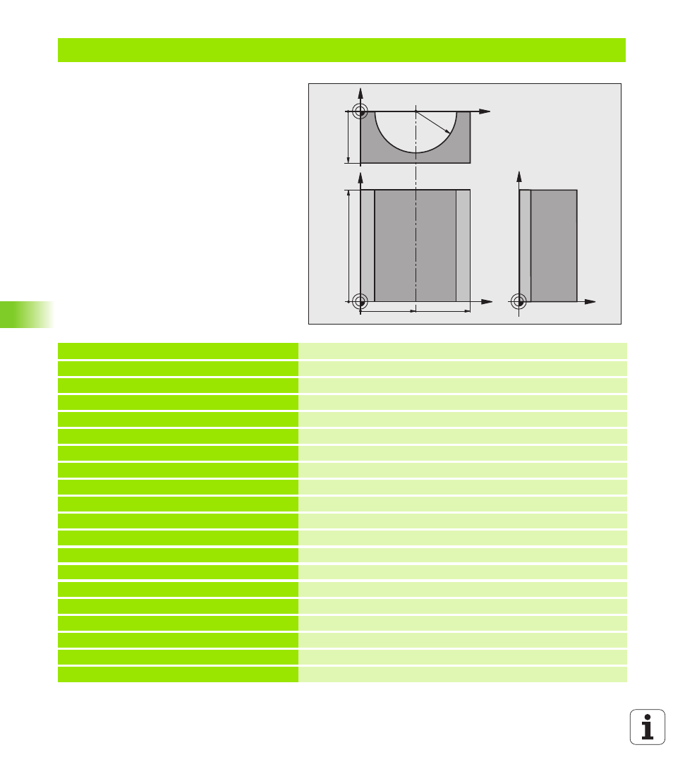
Example: Concave cylinder machined with spherical cutter
Program sequence
Program functions only with a spherical cutter.
The tool length refers to the sphere center.
The contour of the cylinder is approximated by
many short line segments (defined in Q13). The
more line segments you define, the smoother
the curve becomes.
The cylinder is milled in longitudinal cuts (here:
parallel to the Y axis).
The machining direction can be altered by
changing the entries for the starting and end
angles in space:
Clockwise machining direction:
starting angle > end angle
Counterclockwise machining direction:
starting angle < end angle
The tool radius is compensated automatically.
0 BEGIN PGM CYLIN MM
1 FN 0: Q1 = +50
Center in X axis
2 FN 0: Q2 = +0
Center in Y axis
3 FN 0: Q3 = +0
Center in Z axis
4 FN 0: Q4 = +90
Starting angle in space (Z/X plane)
5 FN 0: Q5 = +270
End angle in space (Z/X plane)
6 FN 0: Q6 = +40
Cylinder radius
7 FN 0: Q7 = +100
Length of the cylinder
8 FN 0: Q8 = +0
Rotational position in the X/Y plane
9 FN 0: Q10 = +5
Allowance for cylinder radius
10 FN 0: Q11 = +250
Feed rate for plunging
11 FN 0: Q12 = +400
Feed rate for milling
12 FN 0: Q13 = +90
Number of cuts
13 BLK FORM 0.1 Z X+0 Y+0 Z-50
Definition of workpiece blank
14 BLK FORM 0.2 X+100 Y+100 Z+0
15 TOOL CALL 1 Z S4000
Tool call
16 L Z+250 R0 FMAX
Retract the tool
17 CALL LBL 10
Call machining operation
18 FN 0: Q10 = +0
Reset allowance
19 CALL LBL 10
Call machining operation
X
Y
50
100
100
Z
Y
X
Z
-50
R40