Working plane (cycle 19, software option 1), 7 coor dinat e t ransf or mation cy cles – HEIDENHAIN TNC 620 (340 56x-01) User Manual
Page 355
HEIDENHAIN TNC 620
355
8.7 Coor
dinat
e
T
ransf
or
mation Cy
cles
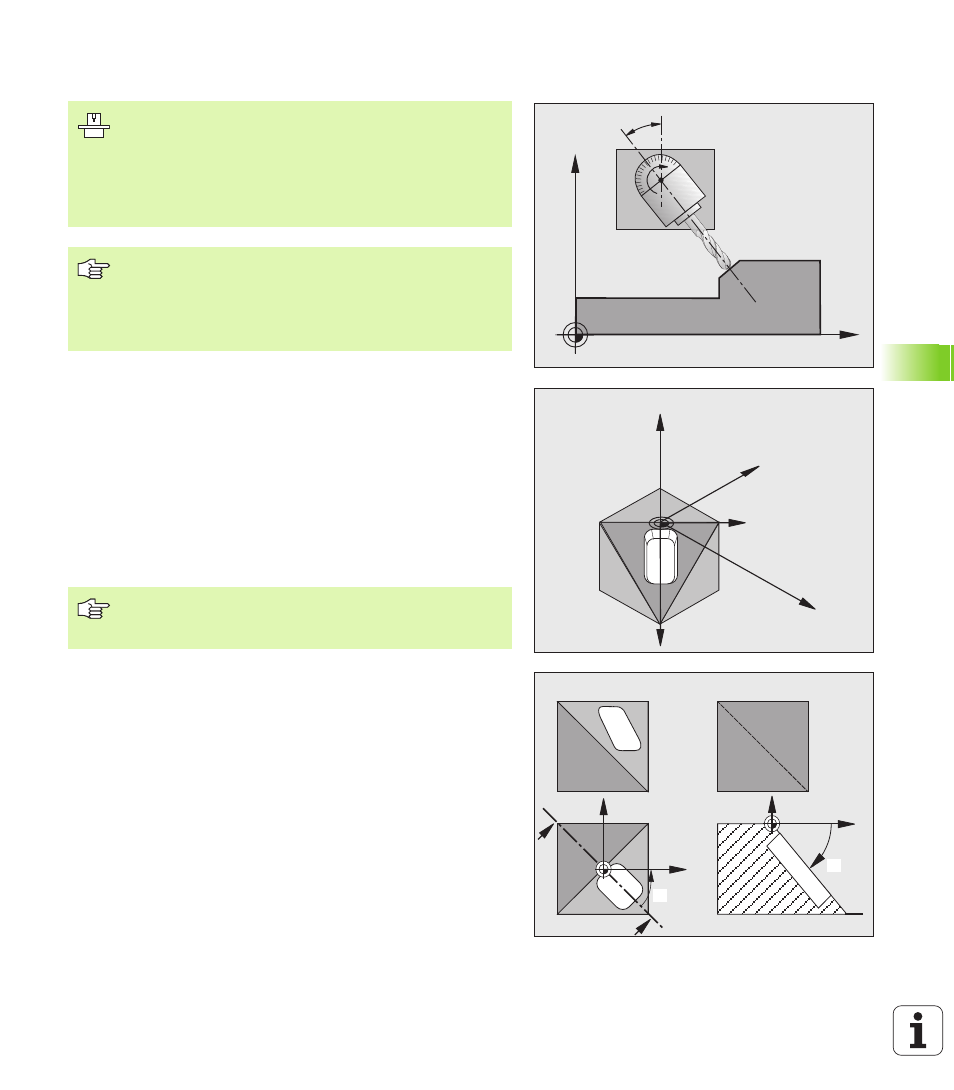
WORKING PLANE (Cycle 19, software option 1)
Effect
In Cycle 19 you define the position of the working plane—i.e. the
position of the tool axis referenced to the machine coordinate
system—by entering tilt angles. There are two ways to determine the
position of the working plane:
Enter the position of the tilting axes directly.
Describe the position of the working plane using up to 3 rotations
(spatial angle) of the fixed machine coordinate system. The
required spatial angle can be calculated by cutting a perpendicular
line through the tilted working plane and considering it from the axis
around which you wish to tilt. With two spatial angles, every tool
position in space can be defined exactly.
Z
X
B
X
Z
Y
X'
Y'
Z
S
S
S-S
X
B
Y
X
C
The functions for tilting the working plane are interfaced to
the TNC and the machine tool by the machine tool builder.
With some swivel heads and tilting tables, the machine
tool builder determines whether the entered angles are
interpreted as coordinates of the rotary axes or as
mathematical angles of a tilted plane. Refer to your
machine manual.
The working plane is always tilted around the active
datum.
For fundamentals, see “Tilting the Working Plane
(Software Option 1),” page 62. Please read this section
completely.
Note that the position of the tilted coordinate system, and
therefore also all movement in the tilted system, are
dependent on your description of the tilted plane.