Linear encoders, Setting the display step, Display step, signal period and subdivision – HEIDENHAIN ND 930 User Manual
Page 40
40
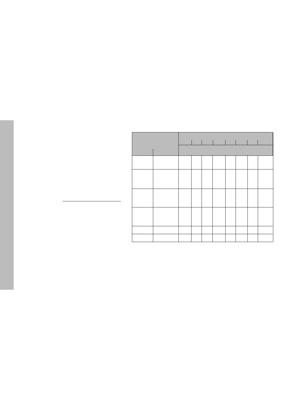
Display step, signal period and subdivision for linear encoders
Display step
P31: Signal period
[µm]
2
2
2
2
2 4 10 20 40 100 20012800
4 10 20 40 100 20012800
4 10 20 40 100 20012800
4 10 20 40 100 20012800
4 10 20 40 100 20012800
[mm]
[inches]
P32: Subdivision
0.000 02 0.000 001 100
–
–
–
–
–
–
–
0.000 05 0.000 002
40
80
–
–
–
–
–
–
0.000 1
0.000 005
20
40
100
–
–
–
–
–
0.000 2
0.000 01
10
20
50 100
–
–
–
–
0.000 5
0.000 02
4
8
20
40
80
–
–
–
0.001
0.000 05
2
4
10
20
40
100
–
–
0.002
0.000 1
1
2
5
10
20
50
100
–
0.005
0.000 2
0.4
0.8
2
4
8
20
40
–
0.01
0.000 5
0.2
0.4
1
2
4
10
20
–
0.02
0.001
–
–
0.5
1
2
5
10
–
0.05
0.002
–
–
0.2
0.4
0.8
2
4
–
0.1
0.005
–
–
0.1
0.2
0.4
1
2
128
0.2
0.01
–
–
–
–
–
–
–
64
Linear Encoders
Linear Encoders
Setting the display step with linear encoders
The display step depends on the
•
signal period of the encoder (P31) and the
•
subdivision (P32).
Both parameters are entered separately for each
axis.
For linear measurement using nut/ballscrew
arrangements and rotary encoders, calculate the
signal period as follows:
Signal period [µm] =
Drivescrew pitch [mm] x 1000
Line count