2 emergency stop flowchart – HEIDENHAIN TNC 122 Technical Manual User Manual
Page 36
4/97
TNC 122
9 Machine Integration
35
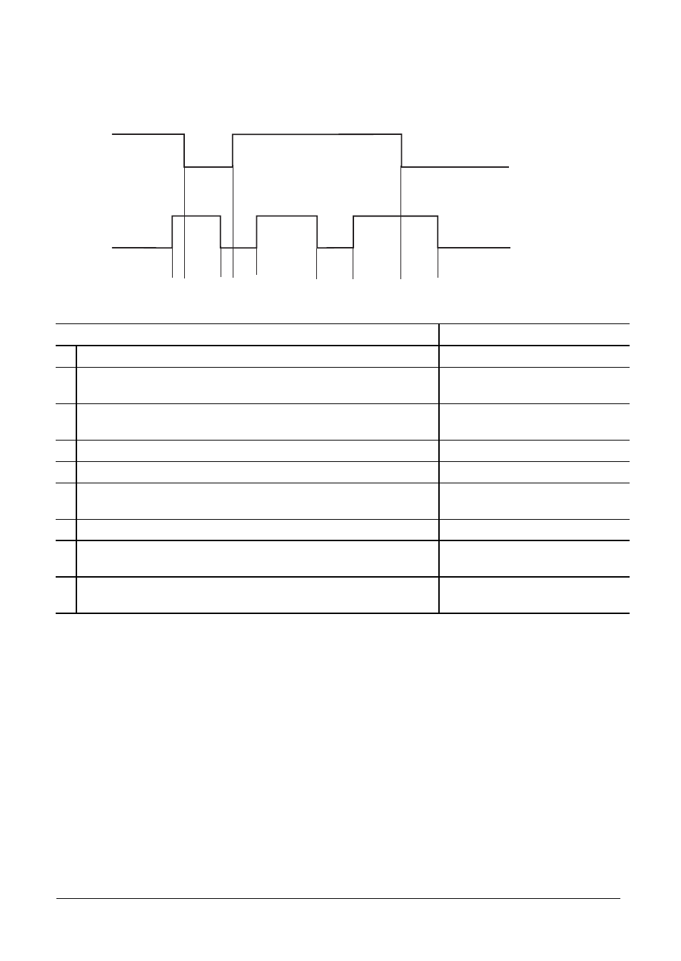
9.7.2 EMERGENCY STOP Flowchart
The external electronics must fulfill the prescribed basic requirements. In particular, the
acknowledgment for “control is ready” must be received within 200 ms.
X41/10
X41/28
1 2 3 4 5 6 7 8 9
Display
1
Waiting for control voltage.
NO CONTROL VOLTG
2
Recognition of the control voltage at X41/28 and reset control-
is-ready output at X41/10.
3
Maximum time until control-is-ready signal at X41/28 must go
to 0 (t < 200 ms). If time limit is exceeded, error message:
EMERG STOP DEFEC
4
Recognition of acknowledgment, output X41/10 set.
5
Waiting for control voltage.
NO CONTROL VOLTG
6
Normal control operation. Output and control-is-ready
acknowledgment are set.
7
Control voltage switched off by external event.
EMERGENCY STOP
8
When the control voltage is switched on again the error
message can be cleared; then return to normal operation.
9
If an error is detected, the control switches off the control-is-
ready output (X41/10).
Blinking error message