Router, Installation, Making alarm connections – Grass Valley NV8288 v.1.5 User Manual
Page 60
50
Rev 1.5 • 24 Sep 09
3. Installation
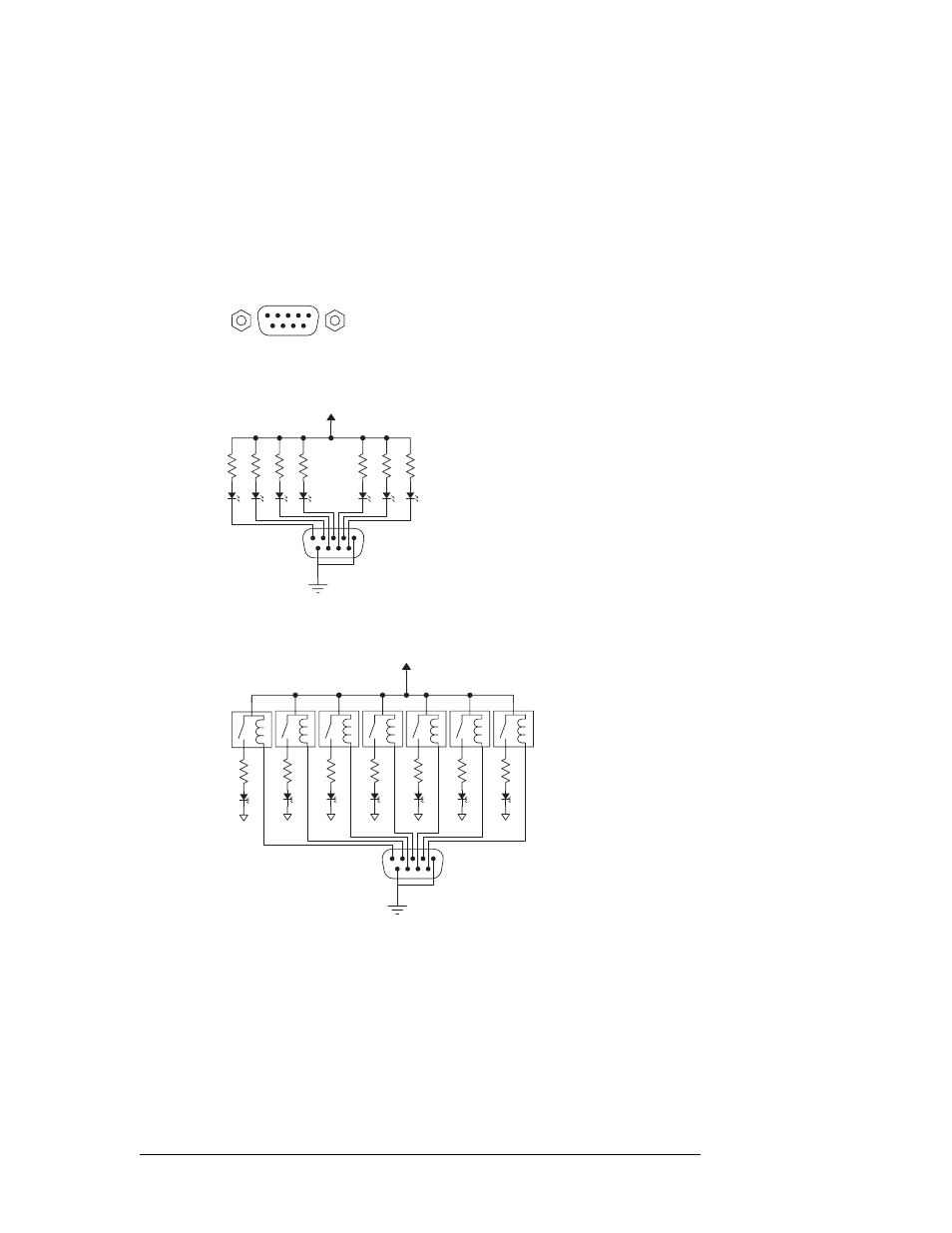
Making Alarm Connections
Router
The ‘ALARM’ connection on the rear of the router uses a DE9 connector. An “alarm” or ON con-
dition occurs when the connection between an alarm pin and Alarm_COM (common) opens. The
alarm turns OFF when the connection between Alarm_COM and the alarm pin closes again.
For an external alarm indicator box, connect to the ‘ALARM’ connection using a DE9 female con-
nector, wiring as shown in Figure 3-25. Each pin monitors a specific function and activates a spe-
cific alarm.
Figure 3-25. Alarm Connections and On/Off Switches
Typical Circuit 1
Customer-supplied relay
contacts NC, (but open during
alarm condition)
External Power,
30VDC max, 150mA max
Normally ON, the LEDs turn off to indicate failure
1
COM
Normally OFF, the LEDs turn on to indicate failure
30VDC max, 150mA max
External Power
1
1
2
3
4
5
6
7
8
9
1
2
3
4
5
Alarm COM
Alarm 1
Alarm 2
Alarm 3
Alarm 4
8
7
8
9
Alarm 5
Alarm 6
Alarm 7
Alarm COM
Typical Circuit 2
COM