Installation, Making power connections – Grass Valley NV8288 v.1.5 User Manual
Page 38
28
Rev 1.5 • 24 Sep 09
3. Installation
Making Power Connections
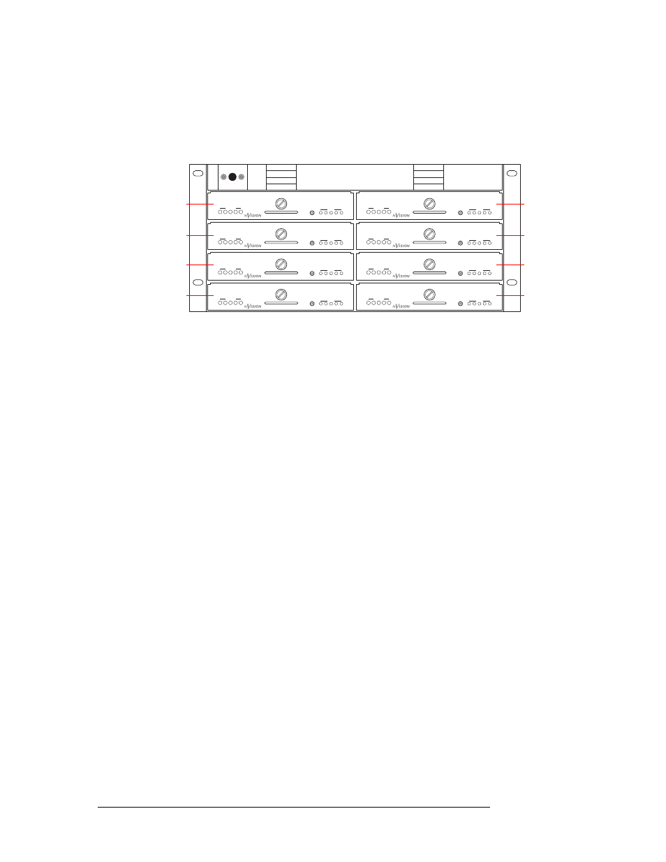
a Facing the front of the NV6257, install the primary PS6000 power supply modules in slots
PS 1, PS 3, PS 5 and PS 7, as shown in Figure 3-3.
b (Optional) Facing the front of the NV6257, install the redundant PS6000 power supply
modules in slots PS 2, PS 4, PS 6 and PS 8, as shown in Figure 3-3.
Figure 3-3. NV6257 Power Supply (Front View)
8 Facing the rear of the router, connect the ground lug to ground using a copper wire from 14 to
6 AWG. The ground lug is located in the lower, right-hand corner of the frame.
How to Connect a Single NV6257 to a Single NV8288-Plus Frame
1 Locate the power cords, PS6000 power supply modules, and cables.
2 Facing the rear of the NV6257, connect one end of the power supply cable (WC0085) to ‘Out-
put Power 2’, as shown in Figure 3-1 on page 27.
3 Facing the rear of the router, connect the other end of the power supply cable to ‘Power Input’,
as shown in Figure 3-2 on page 27.
4 Facing the rear of the NV6257, connect one end of the monitor cable (WC0046) to the ‘Power
Supply Monitors’ DB25 connection, as shown in Figure 3-1 on page 27.
5 Facing the rear of the router, connect the other end of the monitor cable to ‘Power Supply
Monitor’, as shown in Figure 3-2 on page 27.
6 Facing the rear of the NV6257, connect power cords from an AC power source (90–230 VAC,
50–60 Hz) into power supply connections PS 1 through PS 4, as shown in Figure 3-1 on
page 27. Connect one power cord for each PS6000 power supply module installed. (See step 7.)
7 Install the PS6000 power supply modules as follows:
a Facing the front of the NV6257, install the primary PS6000 power supply modules in slots
PS 1 and PS 3, as shown in Figure 3-3 on page 28.
b (Optional) Facing the front of the NV6257, install the redundant PS6000 power supply
modules in slots PS 2 and PS 4, as shown in Figure 3-3.
8 Facing the rear of the router, connect the ground lug to ground using a copper wire from 14 to
6 AWG. The ground lug is located in the lower, right-hand corner of the frame.
PS5
PS6
PS7
PS8
PS1
PS2
PS3
PS4
GND
POWER
1
2
3
4
5
1
2
3
4
5
+
48V
PS6000
GND
POWER
1
2
3
4
5
1
2
3
4
5
+
48V
PS6000
GND
POWER
1
2
3
4
5
1
2
3
4
5
+
48V
PS6000
GND
POWER
1
2
3
4
5
1
2
3
4
5
+
48V
PS6000
GND
POWER
1
2
3
4
5
1
2
3
4
5
+
48V
PS6000
GND
POWER
1
2
3
4
5
1
2
3
4
5
+
48V
PS6000
GND
POWER
1
2
3
4
5
1
2
3
4
5
+
48V
PS6000
GND
POWER
1
2
3
4
5
1
2
3
4
5
+
48V
PS6000
POWER
POWER
POWER
POWER
POWER
POWER
POWER
POWER
GND
GND
GND
GND
GND
GND
GND
GND
Primary PS (1)
Redundant PS (2)
Primary PS (3)
Redundant PS (4)
Primary PS (5)
Redundant PS (6)
Primary PS (7)
Redundant PS (8)