Ethernet control system connections, Control system expansion connections, Instructions, see – Grass Valley NV8288 v.1.5 User Manual
Page 50: Ethernet control system connec, Tions, S, see, Control system expansion, Connections, Control system expan, Sion connections
40
Rev 1.5 • 24 Sep 09
3. Installation
Making Router Control System Connections
Ethernet Control System Connections
Ethernet control connections connect the router to the router control system using Ethernet connec-
tors. An Ethernet connection is recommended for the NV9000 router control system. Ethernet con-
nections are especially helpful the PC running the router control system is on a network.
The Ethernet ports are divided into two sets that communicate with the primary control card or the
secondary control card. For a detailed description of the Ethernet connections, see
on page 12. Unlike serial control connections, there are no Ethernet connections to
redundant control systems because redundant control systems can be connected through Ethernet
network connections.
In order for the router to communicate with the router control system through an Ethernet connec-
tion, an IP address for the router needs to be set in the control card. For more information, see
The Ethernet control system connections use RJ45 connectors and Cat5, or better, cable. The Ether-
net port is 10/100BT.
How to Make an Ethernet Connection to the Control System
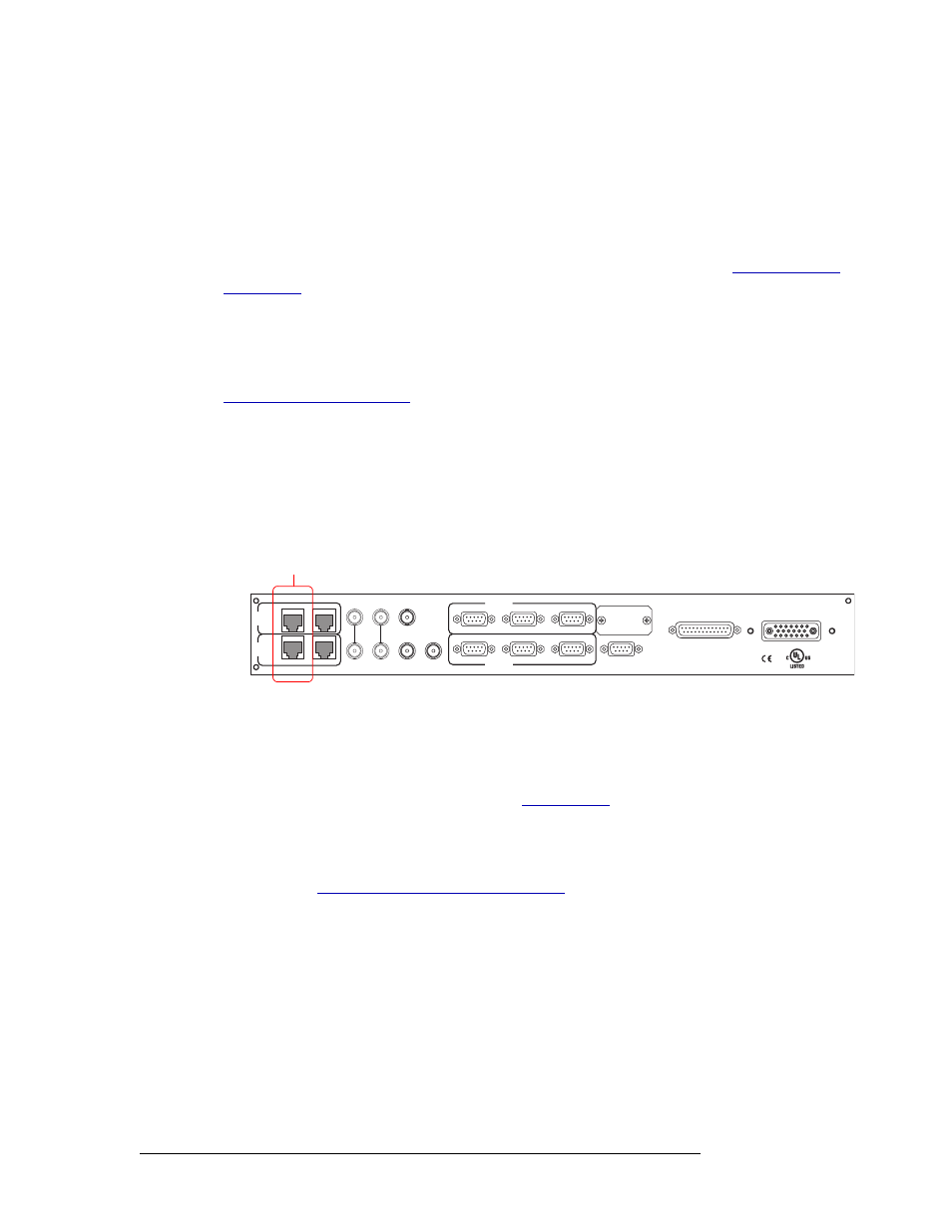
1 Locate the Ethernet connections on the rear of the router, as shown in Figure 3-14. The Ethernet
connections are labeled ‘10/100BT’.
Figure 3-14. Ethernet Connections to Control System (Rear View)
2 Connect to the ‘10/100 BASE T’ Ethernet connection in the ‘PRI CTRL’ section using a RJ45
connector and Cat5, or better, cable.
3 Connect the other end of the cable to an Ethernet hub or switch on the router control system PC.
4 If a secondary (optional for redundancy; see
on page 15) control card is installed,
connect to the ‘10/100 BASE T’ Ethernet connection in the ‘SEC CTRL’ section as described in
Step 2 and Step 3.
5 If connecting two NV8288-Plus routers together, connect the control system expansion connec-
tions. (See
Control System Expansion Connections
, following,)
Control System Expansion Connections
Control system expansion connections enable two connected NV8288-Plus routers to communicate
with the router control system. When making control system connections, only one router is con-
nected directly to the router control system. This router acts as the primary router. When making
control system expansion connections, a separate connection is made from that router to the sec-
ondary router. This enables the router control system to manage both routers through the primary
router connection. For simplicity, this procedure refers to each router as the primary or secondary
router.
RTR EXPANSION
E146905
10/100 BT
10/100 BT
RTR EXPANSION
VIDEO
REF 1
LOOP
VIDEO
REF 2
LOOP
AUX 1
AUX 2
CTRL 1
CTRL 1
CTRL 2
CTRL 2
ALARMS
POWER SUPPLY
MONITORS
POWER INPUT
TIME
CODE
PRI
CTRL
SEC
CTRL
PRI CTRL
SEC CTRL
DIAG (38.4 Kbaud)
DIAG (38.4 Kbaud)
Ethernet Connections
to Router Control System