Installation – Grass Valley NV8288 v.1.5 User Manual
Page 49
NV8288 and NV8288-Plus Digital Video Routers • User’s Guide
39
3. Installation
Making Router Control System Connections
(i.e., backup system) or to set up dual control, if desired. For a detailed description of the serial con-
trol connections, see
Serial control connections use SMPTE 207M DE9 connectors (RS-422/489) and serial cable.
How to Make Serial Control Connections
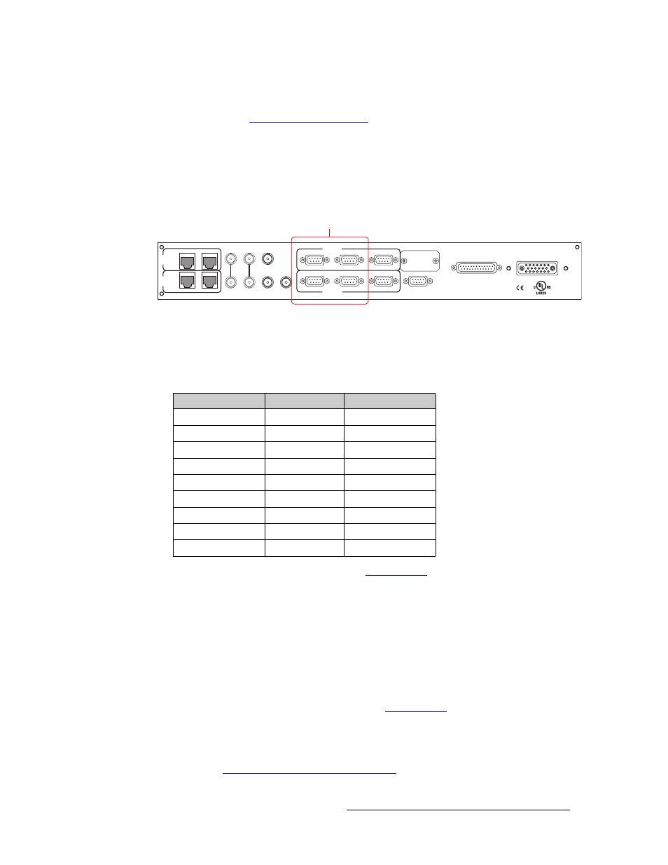
1 Locate the serial control connections on the rear of the router, as shown in Figure 3-13. Serial
control connections are labeled ‘PRI CTRL’ and ‘SEC CTRL’.
Figure 3-13. Serial Control Connections to Control System (Rear View)
2 Connect to the ‘CTRL 1’ connection in the ‘PRI CTRL’ section using a DE9 connector and
serial cable.
3 Connect the other end of the cable to the (primary) router control system using a DE9 connec-
tor. The following is a list of DE9 wiring for the connectors:
4 If a secondary (optional for redundancy, see
on page 15) control card is installed,
connect to the ‘CTRL 1’ connection in the ‘SEC CTRL’ section as described in steps 2 and 3.
5 If an alternate control system (e.g., for redundancy or dual control) is being used, make connec-
tions as follows:
a Connect to the ‘CTRL 2’ connection in the ‘PRI CTRL’ section using a DE9 connector and
serial cable.
b Connect the other end of the serial cable to the secondary router control system using a DE9
connector. Wire connectors as described in Step 3.
c If a secondary (optional for redundancy; see
on page 15) control card is
installed, connect to the ‘CTRL 2’ connection in the ‘SEC CTRL’ section using a DE9 con-
nector and serial cable as described in steps 5a and 5b.
6 If connecting two NV8288-Plus routers together, connect the control system expansion connec-
tions. (See
Control System Expansion Connections
RTR EXPANSION
E146905
10/100 BT
10/100 BT
RTR EXPANSION
VIDEO
REF 1
LOOP
VIDEO
REF 2
LOOP
AUX 1
AUX 2
CTRL 1
CTRL 1
CTRL 2
CTRL 2
ALARMS
POWER SUPPLY
MONITORS
POWER INPUT
TIME
CODE
PRI
CTRL
SEC
CTRL
PRI CTRL
SEC CTRL
DIAG (38.4 Kbaud)
DIAG (38.4 Kbaud)
Serial Connections
to Router Control System
Control End
Pins
Router End
Ground
1 ------------1
Ground
Rx–
2 ------------2
Tx–
Tx+
3 ------------3
Rx+
Tx Common
4 ------------4
Rx Common
N/C
5 ------------5
N/C
Rx Common
6 ------------6
Tx Common
Rx+
7 ------------7
Tx+
Tx –
8 ------------8
Rx–
Ground
9 ------------9
Ground