Power on the l30 raid chassis, Setting up the l30 raid chassis, Primary expansion 1 expansion 2 – Grass Valley K2 Storage System Instruction Manual v.3.2 Nov.18 2008 User Manual
Page 253: Dp0 dp1, Sas cables
July 15, 2008
K2 Storage System Instruction Manual
253
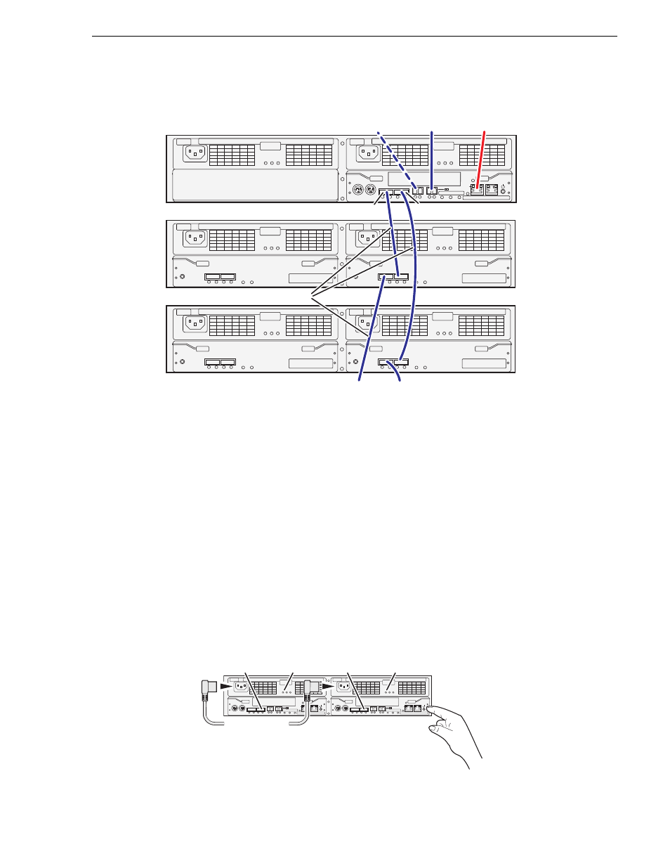
Setting up the L30 RAID chassis
If you have more Expansion chassis than those illustrated, continue the indicated
cabling pattern, alternating connections for additional Expansion chassis between
DP1 and DP0. Expansion chassis 1, 3, 5, 7, etc. (odd numbers) connect to DP1.
Expansion chassis 2, 4, 6, 8, etc. (even numbers) connect to DP0. For example, if you
have four Expansion chassis (an even number), they are evenly balanced, so you have
two connected to DP1 and two connected to DP0. If you have five Expansion chassis
(an odd number), the “plus one” Expansion chassis is always connected to DP1, so
you have three connected to DP1 and two connected to DP0.
Power on the L30 RAID chassis
Connect power cords and power up RAID storage devices as follows:
1. Verify power and cabling.
2. Press and hold down the power button on the controller, as shown.
FLT/LNK
FLT
RDY
DP-OUT
PS
FLT CLR
DP-IN
FLT/LNK
FLT
RDY
DP-OUT
PS
FLT CLR
DP-IN
FLT/LNK
FLT
RDY
DP-OUT
PS
FLT CLR
DP-IN
FLT/LNK
FLT
RDY
DP-OUT
PS
FLT CLR
DP-IN
BBU IN
MODEM
FLT/LNK
HPE
FLT
A/L
BACKUP
ACT/LNK
LNK/ACT
FLT
HP
5 4 3 2
RDY
LAN
BAT
MNT
ACS
MC
DP1
DP0
HP
1 0
BBU IN
MODEM
FLT/LNK
HPE
FLT
A/L
BACKUP
ACT/LNK
LNK/ACT
FLT
HP
5 4 3 2
RDY
LAN
BAT
MNT
ACS
MC
DP1
DP0
HP
1 0
Primary
Expansion 1
Expansion 2
DP0
DP1
To
Expansion
3
To
Expansion
4
To control port
on GigE switch
To K2 Media
Server A
To NH server
(optional)
SAS cable connectors are keyed to DP IN/OUT ports.
SAS cables
BBU IN
MODEM
FLT/LNK
HPE
FLT
A/L
BACKUP
ACT/LNK
LNK/ACT
FLT
HP
5 4 3 2
RDY
LAN
BAT
MNT
ACS
MC
DP1
DP0
HP
1 0
BBU IN
MODEM
FLT/LNK
HPE
FLT
A/L
BACKUP
ACT/LNK
LNK/ACT
FLT
HP
5 4 3 2
RDY
LAN
BAT
MNT
ACS
MC
DP1
DP0
HP
1 0
Power Cords
(115V/230V)
RDY
LED
RDY
LED
Power Good
LED
Power Good
LED